slanina
Junior Member level 2
Hello all,
I am desiging a circuit that will interface with the Allegro A1301 linear Hall sensor.
This sensor works at 5V and outputs Vcc/2 (2.5V) in neutral case - no magnetic field.
It has a sensitivity of 2.5mV/G.
I will interface this sensor to an ARM Cortex MCU that has a 10-bit ADC 0-3.3v range on board.
At 3.3V with 10-bits I get 3.22mV per ADC step, which means my sensor has more resolution than my ADC.
I am interested in measuring A1301 only the sensor output values between 2-3V, thus corresponding to 200 Gauss change either way and then I would scale this sensor output range to the full ADC range prior to conversion, so I get good resoultion.
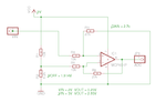
I have designed a simple circuit for this:

Due to standard resistor sizes being used I am OK with Vref to be 1.9V so my range will be slightly more than 2-3V.
How can I make sure that input to ADC is not over 3.3V? Because even though I am interested in 2-3V range, it can happen that sensor output goes to 4V or more (in case there is some strong magnet close by) which would fry the ADC. Similarly, sensor output can drop to 0, which would make op amp voltage output negative.
Should I feed sensor output first to a voltage divider (10k/18k) and then to this circuit (with different resistor values now) or should I use clamping zener diodes before the ADC as suggested on some other threads ? However, I would not like to add noise to my signal.
As for constraints - there is single power supply (5V and 3.3V is available).
Any suggestions? Thanks.
I am desiging a circuit that will interface with the Allegro A1301 linear Hall sensor.
This sensor works at 5V and outputs Vcc/2 (2.5V) in neutral case - no magnetic field.
It has a sensitivity of 2.5mV/G.
I will interface this sensor to an ARM Cortex MCU that has a 10-bit ADC 0-3.3v range on board.
At 3.3V with 10-bits I get 3.22mV per ADC step, which means my sensor has more resolution than my ADC.
I am interested in measuring A1301 only the sensor output values between 2-3V, thus corresponding to 200 Gauss change either way and then I would scale this sensor output range to the full ADC range prior to conversion, so I get good resoultion.
I have designed a simple circuit for this:

Due to standard resistor sizes being used I am OK with Vref to be 1.9V so my range will be slightly more than 2-3V.
How can I make sure that input to ADC is not over 3.3V? Because even though I am interested in 2-3V range, it can happen that sensor output goes to 4V or more (in case there is some strong magnet close by) which would fry the ADC. Similarly, sensor output can drop to 0, which would make op amp voltage output negative.
Should I feed sensor output first to a voltage divider (10k/18k) and then to this circuit (with different resistor values now) or should I use clamping zener diodes before the ADC as suggested on some other threads ? However, I would not like to add noise to my signal.
As for constraints - there is single power supply (5V and 3.3V is available).
Any suggestions? Thanks.