Continue to Site

Welcome to EDAboard.com

Welcome to our site! EDAboard.com is an international Electronics Discussion Forum focused on EDA software, circuits, schematics, books, theory, papers, asic, pld, 8051, DSP, Network, RF, Analog Design, PCB, Service Manuals... and a whole lot more! To participate you need to register. Registration is free. Click here to register now.

Voltage regulator output drop with the negative feedback resistor

Status
Not open for further replies.

Junus2012

Advanced Member level 5
Joined
Jan 9, 2012
Messages
1,552
Helped
47
Reputation
98
Reaction score
53
Trophy points
1,328
Location
Italy
Activity points
15,235
Dear friends,

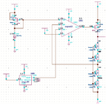
I am using the basic voltage regulator to provide a stable voltage , please see the image below
as in general, it is in principle non-inverting amplifier with input terminal swapped because I used PMOS pass transistor.
here you can see that that the gain is 1+20k*20k = 2, and I connected bandgap reference voltage at the input so the output is 2.45 V, which is perfectly achieved in the circuit DC operation.
I have tried to increase the resistors by using 40 k instead of 20 k, and the result is more vaiation in the regulated output as compared to the former one with 20 k,
Why this is happening?

I tried to be little smart and I connected fat capacitor at the output, and every thing is screwed as I have like oscillated output.

Also I would like to ask you about the pass transistor, what is rule for sizing it?

thank you

reg.png
 

Another schematic that is a black negative image that is hard to see anything. I inverted it so that it is a normal positive image and boosted its contrast.

But the schematic has its parts very far apart which makes text so tiny that it cannot be seen in the mess of background dots.

Here is the inverted image with increased contrast:
 

Attachments

  • v reg (2).png
    v reg (2).png
    120.5 KB · Views: 144

    Junus2012

    Points: 2
    Helpful Answer Positive Rating
Another schematic that is a black negative image that is hard to see anything. I inverted it so that it is a normal positive image and boosted its contrast.
Thank you very much Audio

When you say more variation with 40k resistors, what do you mean? DC variation, MC variation?
Thanks Suta, I mean in the transient, the regulated voltage is used to drive a ring oscillator, so in the time of logic transition it start to drop then settle in the steady state, that is expected because the in the transition time switches conduct high current, so I have no objection on this. But when I tried to reduce the load on the opamp by connecting 40 kOhm instead the 20 k, the drop becomes more
 

The drop depends on the speed of recovery of the loop after a step current load change. Reducing the current, reduces the speed, so more drop. As you said previously, you can put more capacitance but you have to make it stable.
 
The drop depends on the speed of recovery of the loop after a step current load change. Reducing the current, reduces the speed, so more drop. As you said previously, you can put more capacitance but you have to make it stable.
Thank you Suta,

it is becomign little confusing for me
I didn't reduce the biasing current, I reduced the load current, how this can effect the speed?

two more questions please as I am no too much in to the LDO bu I rea that link you suggested me

1. What about driving the load without passing transistor, simply like non inverting amplifier driving a load, I tried it and it working perfectly

2. if adding cap cause unstability, so may be using OTA driving the pass transistor is better because more cap will make him even more stable
 

Well, my way of thinking is that you changed the bias current in the output stage i.e. the pass transistor. That is the biasing when the load current is 0. You actually dropped it by 2x. Of course, I haven't done the math but this should affect the speed. This output stage is part of the loop.

Yes, if you can drive your load with just an OTA, that's perfectly fine. You are right that adding a bigger cap will decrease variations and make the OTA more stable. It is a matter of how much load current you have, how much headroom you have and so on.
Do you mean to say it is ok to drive it using simple non-inverting amplifier without adding passing transistor is ok?
in this case the amplifier will be responsible on delivering the total load current and I have buffered one that he can do
 

That's why I said that it's a matter of how much load current you need to provide and how much headroom you have.
 

    Junus2012

    Points: 2
    Helpful Answer Positive Rating
Status
Not open for further replies.

Part and Inventory Search

Welcome to EDABoard.com

Sponsor

Back
Top