Continue to Site

Welcome to EDAboard.com

Welcome to our site! EDAboard.com is an international Electronics Discussion Forum focused on EDA software, circuits, schematics, books, theory, papers, asic, pld, 8051, DSP, Network, RF, Analog Design, PCB, Service Manuals... and a whole lot more! To participate you need to register. Registration is free. Click here to register now.

voltage follower, op-amp

Status
Not open for further replies.

beaver

Junior Member level 1
Joined
Aug 2, 2009
Messages
16
Helped
0
Reputation
0
Reaction score
0
Trophy points
1,281
Activity points
1,410
voltage follower op amp

Hi, everyone!

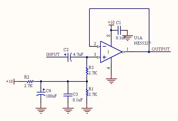
I want to build a voltage follower with NE5532. One requirement is that the op amp should be supplied with a single power.

My design is:


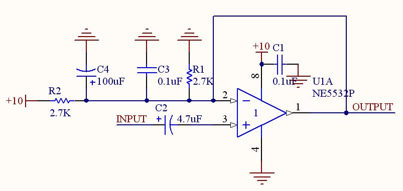
The output, however, suffers from great distortion and attenuation. Can anybody help me out?

Thank you in advance.
 

voltage follower

There is a fundamental error in your circuit:
Biasing is not OK. Place a voltage divider (2 equal resistors) in front of the + input and inject the input signal through a capacitor and establish 100% feedback. That´s all.
 

op amp voltage follower

Hi, LvW!

I changed the circuit as follows


But I don't know how R3 works. Can you tell me? Thank you!
 

follower op amp

Good question. Can be answered only by you because YOU have decided to use R3.
(It makes no sense - delete it, unless you like to increase your input resistance.
In this case you even can increase the value).
 

voltage follower opamp

Hi, LvW!

Thank you for your reply. I drew my inspiration of R3 from (**broken link removed**). Also, in the datasheet of LM1875, the configuration they recommended is
74_1250947606.jpg

and there is also a R3.

According to my experiment, if R3 is deleted, the circuit cannot work.

Thus I think R3 is critical here, but I don't know in what way.
 

voltage follower op amp circuit

LvW suggested a simple resistive divider (R1/R2) without bypass capacitors (C3/C4). With capacitors, also R3 is required, otherwise you short the input signal.

The purpose of the bypass capacitors and R3 is in preventing supply voltage interferences from entering the signal path. You should know, if it may be meaningful in your application. The LM1875 reference circuit is apparently taking acount of possible 100/120 Hz interferences from an incompletely filtered mains supply.
 

    beaver

    Points: 2
    Helpful Answer Positive Rating
voltage follower circuit

Your resistor values are way too low. Use 100k for each of them then the input capacitor can be a 0.1uf film one and the input impedance will be high enough for almost anything to feed it.
 

voltage follower

LvW said:
Good question. Can be answered only by you because YOU have decided to use R3.
(It makes no sense - delete it, unless you like to increase your input resistance.
In this case you even can increase the value).

in that circuit, you HAVE to have R3 for the circuit to work: R3 defines the (ac) input impedance of the circuit. With R3, the input is essentially (ac) grounded.
 

Status
Not open for further replies.

Similar threads

Part and Inventory Search

Welcome to EDABoard.com

Sponsor

Back
Top