Continue to Site

Welcome to EDAboard.com

Welcome to our site! EDAboard.com is an international Electronics Discussion Forum focused on EDA software, circuits, schematics, books, theory, papers, asic, pld, 8051, DSP, Network, RF, Analog Design, PCB, Service Manuals... and a whole lot more! To participate you need to register. Registration is free. Click here to register now.

Voltage Drop in input of PIC16F887 when connected to MOSFETs in bridge.

Status
Not open for further replies.

Rajkeen

Newbie level 4
Joined
Mar 30, 2015
Messages
6
Helped
0
Reputation
0
Reaction score
0
Trophy points
1
Activity points
41
Hello everyone,
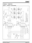
I'm working on speed control of BLDC motor as final year project.I have used Pic16f887 IC for control purpose.I have referred datasheet provided by Microchip AN857.I have made entire circuit as shown in it except used 887 instead po PIC16F877.
Now my problem is,when I connect the MOSFET bridge with the PIC through drivers TC4469 there is sudden voltage drop in input of PIC from 4.8V to 3V as a result PIC is not working.
Please someone let me know what error is.
 

Hi,

what input do you mean. A PIC has a lot of inputs.


Klaus
 

Hi,

what input do you mean. A PIC has a lot of inputs.


Klaus


THe supply of 5V which I provide to power the pic drops when connected to MOSFET bridge
 

Hi,

then either you draw too much power or your power supply is too weak for your load.

What says the current meter?

Klaus
 

Hi,
The mistake I was doing was connecting the MOSFET's in bridge.Since the high channel is P I needed to connect source to supply instead I connected drain.That was causing a short circuit.I had read the datasheet wrongly.
 

Attachments

  • Capture.PNG
    Capture.PNG
    92 KB · Views: 107

Check for crossover time or deadtime under load start , stop or reverse, as it may get worse with shoot-thru spikes. Then ensure delays are used to ensure 1us deadtime approx. worst case.
 

Hi,

The mistake I was doing was...

Is it solved now?
Or do you need further assistance?

Klaus
 

Hello,

For your application, you might be better off using pics which have a complementary waveform generator module. This would make your software and timing related issues much easier to resove.

**broken link removed**

Regards,

Anand
 

Hello,

Now my MOSFETs are working good,but for motor application I need to provide 24V,the MOSFET bridyonege works well on 12 and also on 24V but it gets heated very soon.Any solution for instant heating?
Also when I cannoect bridge to Motor it works till 30 degrees only after that it stops,for eevry change in hall sensor output pic16f887 doesnt get hall output until it is reset.Any suggestions??

Thanks in advance
 

Hi,

could it be that hall sesors are not wired correctly or have to be inverted?

Klaus
 

Hi,

could it be that hall sesors are not wired correctly or have to be inverted?

Klaus
hi,

I have connected the sensor output as shown in the datasheet provided by Michrochip AN857.WHta do you mean by inverting the hall sensor?? and why??
 

Hi,

the hall sensor are mounted ech 120° phase difference to each other. In a way you can use them for commutation information.
Some hall outputs are_active high, some are active_low. Therfore some need to be inverted, some not.

Klaus
 

Hi,

the hall sensor are mounted ech 120° phase difference to each other. In a way you can use them for commutation information.
Some hall outputs are_active high, some are active_low. Therfore some need to be inverted, some not.

I didn't found some specification of hall sensor to be inverted or not,how to check it.
I think there is some error in program,I have attached text file of my program pls check.I m using timer to control seed instead of PWM.
 

Attachments

  • main.txt
    1.6 KB · Views: 37
  • system.txt
    982 bytes · Views: 33
  • Interrupts.txt
    1.3 KB · Views: 39
  • congiguratins.txt
    3.2 KB · Views: 32

Status
Not open for further replies.

Similar threads

Part and Inventory Search

Welcome to EDABoard.com

Sponsor

Back
Top