Continue to Site

Welcome to EDAboard.com

Welcome to our site! EDAboard.com is an international Electronics Discussion Forum focused on EDA software, circuits, schematics, books, theory, papers, asic, pld, 8051, DSP, Network, RF, Analog Design, PCB, Service Manuals... and a whole lot more! To participate you need to register. Registration is free. Click here to register now.

Vintage Motorcycle Ignition Replacment

Status
Not open for further replies.

ElectroNovice

Newbie
Joined
Mar 5, 2023
Messages
4
Helped
0
Reputation
0
Reaction score
0
Trophy points
1
Activity points
41
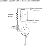
I am looking to replace the old mechanical points on a vintage British twin motorcycle. I have switched over the polarity to a negative ground to be compatable with several LED's. I have kept the mechanical advance but replaced the cam lobe with a magnet. The magnet acts on a pair of Reed Switches to open and close the timing and are used in turn to switch off and on the current to the ignition coils via a BJT transistor - the Reed switches cannot handle the current needed to drive the coils. In this case I am using a TIP35C whose Base is connected to the Reed Switches which in turn are fed by a positive lead. The Emitter is connected to the negative ground while the Collector supplies the positive terminal of the ignition coil. Two questions remain: I believe I need a resistor ahead of the transistor Base to prevent burning out the transistor. I suspect that I need something in the order of a 100 Ohm resistor with a minimum 2W rating. Is this correct? I also believe a diode placed in reverse bias across the coil terminals is required to protect the transistor from the transient flyback voltage spike created when the coil primary voltage collapses. Again, please correct me as I do not have an electronics background and have jumbled my plans together from reading online and copying a similar postive ground device lacking any protective resistors or diodes.. Having sought advise elsewhere only to receive a litany of conflicting direction as well as my thread hacked to discuss several other alternatives , I believe this to be a more professional forum to post my question. I have tried the commercial electronic ignitions and found them although reliable,not providing any performance improvement. The gain obtained from the transistor's should improve performance. My elementary schematic is attached Thank you
 

Attachments

  • TIP35C_Ign.png
    TIP35C_Ign.png
    17.3 KB · Views: 78

For ignition you -want- the flyback spike, that's the spark energy and it had best make it all the way to the plug, not sneak out the side door. You want a lot higher BVces than TIP35's 60V (A) to 100V (C). I suggest an old time TV horizontal transistor as also meant for flyback-y use (CRT gun voltage from horizontal coils), if nothing for direct automotive ignition apps fails to turn up. In no case do you want a snubber. The condenser in a Kettering ignition is there to let the point gap make it to full open without arcing at the points.
 

Observations:
You are basically correct in all respects and a base current limiting resistor is essential or it will burn out.

Note that a reed switch will probably 'bounce' it's contacts so you may get irregular timing and they also have limited speed and lifetimes. You may be operating it tens of times per second so it probably wont last long. A 'Hall sensor' would be a better switch as it has no moving parts.

The other issue is the flyback spike. The diode is essential to protect the transistor from high voltage but remember it's high voltage you actually want. A higher voltage rated transistor might do the job, maybe a BU2506 or similar and omitting the diode or replacing it with a snubber network.

Consider what happens when the switch opens, ideally the base voltage will drop to zero immediately but in real life, leaving the base disconnected will leave some voltage on it from internal leakage and stored charge. You would have to add a resistor between the base and emitter (ground) to leak the charge away. To do it quickly the resistor needs to be fairly low in value, maybe 470 Ohms or less.

Brian.
 

In the ideal case the "breakdown" of the spark gap will
be where all the inductor energy goes, and is the final
limiter of collector / point-gap voltage.

Of course there needs to be margin against spark gap
erosion, fouling and so on, and it would be nice if a
plug wire off the plug didn't eat ignition transistors.
And breakover voltage is going to be higher than
what you measure (if you measure at all) with a fully
compressed cylinder charge and a cold chamber.

There's also the potential to ruin the coil from winding
arc if there's nothing to hold down the voltage against
an open circuit fault.
 

Reed switches can be good for millions of operation if they carry low current.
To do that you can add an emitter-follower transistor, controlled by the reed switch, to provide the power transistor base current.
The base current should be about 1/10th of the collector current for good saturation.
What is the coil current and voltage?
I have tried the commercial electronic ignitions and found them although reliable,not providing any performance improvement.
It is quite unlikely that your homemade circuit will show any performance improvement over the commercial systems.
Electronic ignition system generally provide little improvement in engine power, except perhaps for racing engines.
They mostly are just to improve reliability and eliminate maintenance requirements.
 

The coils are stock Lucas ignition coils in a 12V sytem but they are specked up to 14V , I believe we are talking about 4 Amps draw.
 

I would try to find a club/forum for that motorcycle and ask their suggestions for a proven trough years replacement. I suggest optical (photointerrupters) instead of inductive/points/reed... Play with other projects as a novice.

Some decent, some ripoffs, some... ----> https://www.ecosia.org/search?q=motorcycle ignition optical aftermarket
--- Updated ---

Ignore 'performance' goals; these are reliability items as crutschow mentions.
Twin ? ----> https://www.lowbrowcustoms.com/coll...n-for-triumph-bsa-norton-twin-12v-motorcycles
 
Last edited:

You say you swapped the polarity so I assume you have a battery in the circuit. A workable alternative is to add capacitor discharge ignition, it will show an improvement in performance and better still, it makes starting it easier. I'm guessing you have kick start and one of its problems is the spark is weaker as the engine turns over slowly while starting, CD ignition overcomes that by generating the high voltage first so it is there from the outset. It also saves a lot of leg power and the inevitable skyward launch if the kick isn't quite lined up!

Brian.
 

I hear what you are saying about sticking to reliablity etc. I'm looking for the road less travelled. Thank you for the links. I knew about the various commercial units including Pazon from Lowbrow Customs and others.
 

Betwixt,
I would really like to continue with my home built unit and would switch to a CDI ignition if I knew how to do it. I have several variants of commercial untis in my other bikes sold or still own and I am at the point where i want to do something different.
 

Status
Not open for further replies.

Part and Inventory Search

Welcome to EDABoard.com

Sponsor

Back
Top