eengr
Member level 4
I am working on a VHDL code to generate PWM outputs
For now I would like to generate 50% duty cycle 50kHz waveforms
There are 6 PWM outputs
Each output needs to be 60 degrees out of phase with the previous one (Full cycle is 360 degrees)
So for 50MHz clock input signal, I am using counters for each individual waveform. The counters are incremented by 1 with each rising edge of clock
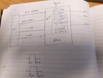
On time scale it should be something like:

So, when counter0 reaches (1000/2 = 500) then PWM(0) goes HIGH
When counter 1 reaches [(1000/6) + (1000/2)] = 666.666 = I used 666 in my code, PWM(1) goes HIGH
And so on...
I used the following VHDL code:
I then used TestBench on ISIM to simulate the code and got the waveforms as below:

The problem I have is that: For the code that I am using I could only use whole number (integers) like 666 (0X29A) instead of 666.666 (or the answer of [(1000/6) + (1000/2)]
This consequently results in slightly different time difference between the waveforms from what they should have been
This could also be seen for the signals:
brick3, brick4, … , brick12 (in my VHDL code)
I am a beginner in VHDL and don’t know the best way to implement this. What is the recommended way / syntax to assign an answer of a function (like [(1000/6) + (1000/2)]) to a signal (say brick3)? Any help would be greatly appreciated
For now I would like to generate 50% duty cycle 50kHz waveforms
There are 6 PWM outputs
Each output needs to be 60 degrees out of phase with the previous one (Full cycle is 360 degrees)
So for 50MHz clock input signal, I am using counters for each individual waveform. The counters are incremented by 1 with each rising edge of clock
On time scale it should be something like:
So, when counter0 reaches (1000/2 = 500) then PWM(0) goes HIGH
When counter 1 reaches [(1000/6) + (1000/2)] = 666.666 = I used 666 in my code, PWM(1) goes HIGH
And so on...
I used the following VHDL code:
Code VHDL - [expand]
I then used TestBench on ISIM to simulate the code and got the waveforms as below:
The problem I have is that: For the code that I am using I could only use whole number (integers) like 666 (0X29A) instead of 666.666 (or the answer of [(1000/6) + (1000/2)]
This consequently results in slightly different time difference between the waveforms from what they should have been
This could also be seen for the signals:
brick3, brick4, … , brick12 (in my VHDL code)
I am a beginner in VHDL and don’t know the best way to implement this. What is the recommended way / syntax to assign an answer of a function (like [(1000/6) + (1000/2)]) to a signal (say brick3)? Any help would be greatly appreciated