awa123
Newbie level 4
Hi,
I am trying to create a power supply that outputs 0-35V using 9V batteries.
I need to be able to vary the voltage while keeping the current as low as possible.
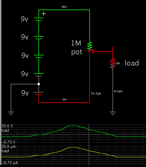
I was thinking a potential divider would work, but I am not sure. Please help, thanks.
I am trying to create a power supply that outputs 0-35V using 9V batteries.
I need to be able to vary the voltage while keeping the current as low as possible.
I was thinking a potential divider would work, but I am not sure. Please help, thanks.