Continue to Site
Follow along with the video below to see how to install our site as a web app on your home screen.
Note: This feature may not be available in some browsers.
#include <p18f4520.h>

void interrupt_at_high_vector(void);
void high_isr(void);

#pragma config OSC = XT //Crystal oscillator
#pragma config WDT = OFF //Watchdog Timer off
#pragma config LVP = OFF //LVP off
#pragma config MCLRE = OFF //MCLR off
unsigned char ADCR;

void main(void){
	CMCON = 7; //DISABLE COMPARATOR
	TRISA = 1; //AN0 INPUT
	TRISC = 0; //CCP1 OUTPUT
	PORTA = 0;
	PORTC = 0;
	ADCON0 = 1; //ADC ON
	ADCON1 = 0x0E; //CH0 ANALOG
	ADCON2 = 0x3E; //20TAD, FOSC/64
	PR2 = 64; //APPROX. 1KHZ
	CCPR1L = 32; //START WITH 50% DUTY CYCLE
	CCP1CON = 0x0C; //PWM
	PIR1 = 0;
	T2CON = 0x04; //START TMR2
	while (1){
		ADCON0bits.GO_DONE = 1; //START CONVERSION
		while (ADCON0bits.GO_DONE); //WAIT FOR END OF CONVERSION
		ADCR = ADRESH; //ADC Result
		ADCR >>= 2; //DIVIDE BY 4 TO BRING TO SCALE OF 64
		while (!PIR1bits.TMR2IF); //WAIT FOR TMR2 INTERRUPT
		CCPR1L = ADCR; //UPDATE DUTY CYCLE
	}
}
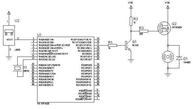
#include <p18f4520.h>

#pragma config OSC = XT //Crystal oscillator
#pragma config WDT = OFF //Watchdog Timer off
#pragma config LVP = OFF //LVP off
#pragma config MCLRE = OFF //MCLR off
unsigned char ADCR, Duty, temp;

void main(void){
	CMCON = 7; //DISABLE COMPARATOR
	TRISA = 1; //AN0 INPUT
	TRISC = 0; //CCP1 OUTPUT
	PORTA = 0;
	PORTC = 0;
	ADCON0 = 1; //ADC ON
	ADCON1 = 0x0E; //CH0 ANALOG
	ADCON2 = 0x3E; //20TAD, FOSC/64
	PR2 = 64; //APPROX. 1KHZ
	CCPR1L = 32; //START WITH 50% DUTY CYCLE
	CCP1CON = 0x0C; //PWM
	PIR1 = 0;
	T2CON = 0x04; //START TMR2
	Duty = 32;
	while (1){
		ADCON0bits.GO_DONE = 1; //START CONVERSION
		while (ADCON0bits.GO_DONE); //WAIT FOR END OF CONVERSION
		ADCR = ADRESH; //ADC Result
		if (ADCR > 20) { //If temperature is greater than 40'C, increase duty cycle
			Duty++;
			if (Duty > 63)
				Duty = 63;
		}
		else { //Else, decrease duty cycle
			Duty--;
			if (Duty < 1)
				Duty = 1;
		}
		while (!PIR1bits.TMR2IF); //WAIT FOR TMR2 overflow
		PIR1bits.TMR2IF = 0;
		CCPR1L = Duty; //UPDATE DUTY CYCLE
		for (temp=0; temp<255; temp++){
			while (!PIR1bits.TMR2IF); //Wait for 10 TMR2 overflows
			PIR1bits.TMR2IF = 0;
		}
	}
}
pl provide me it ASM or hex code in 16f676. plTahmid said:Which language and compiler?
Added after 7 minutes:
Here's a code in C18:
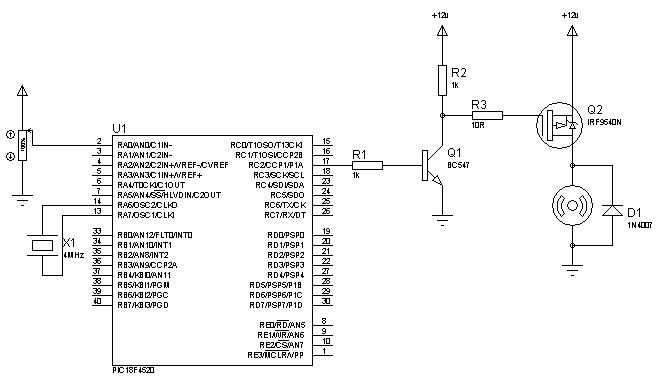
Code:#include <p18f4520.h> void interrupt_at_high_vector(void); void high_isr(void); #pragma config OSC = XT //Crystal oscillator #pragma config WDT = OFF //Watchdog Timer off #pragma config LVP = OFF //LVP off #pragma config MCLRE = OFF //MCLR off unsigned char ADCR; void main(void){ CMCON = 7; //DISABLE COMPARATOR TRISA = 1; //AN0 INPUT TRISC = 0; //CCP1 OUTPUT PORTA = 0; PORTC = 0; ADCON0 = 1; //ADC ON ADCON1 = 0x0E; //CH0 ANALOG ADCON2 = 0x3E; //20TAD, FOSC/64 PR2 = 64; //APPROX. 1KHZ CCPR1L = 32; //START WITH 50% DUTY CYCLE CCP1CON = 0x0C; //PWM PIR1 = 0; T2CON = 0x04; //START TMR2 while (1){ ADCON0bits.GO_DONE = 1; //START CONVERSION while (ADCON0bits.GO_DONE); //WAIT FOR END OF CONVERSION ADCR = ADRESH; //ADC Result ADCR >>= 2; //DIVIDE BY 4 TO BRING TO SCALE OF 64 while (!PIR1bits.TMR2IF); //WAIT FOR TMR2 INTERRUPT CCPR1L = ADCR; //UPDATE DUTY CYCLE } }
Added after 6 minutes:
Here's the circuit for the code.
Hope it helped.
Tahmid.
Added after 20 minutes:
Hi,
If required, I can provide the code in ASM, mikroBASIC or mikroC.