Continue to Site

Welcome to EDAboard.com

Welcome to our site! EDAboard.com is an international Electronics Discussion Forum focused on EDA software, circuits, schematics, books, theory, papers, asic, pld, 8051, DSP, Network, RF, Analog Design, PCB, Service Manuals... and a whole lot more! To participate you need to register. Registration is free. Click here to register now.

using ac isolator for zero crossin in atmega32 mcu

Status
Not open for further replies.

nowfal85

Newbie level 3
Joined
Apr 15, 2007
Messages
4
Helped
0
Reputation
0
Reaction score
0
Trophy points
1,281
Activity points
1,306
triac atmega32

h**p://www.mikrocontroller.net/attachment.php/365292/AN182.pdf

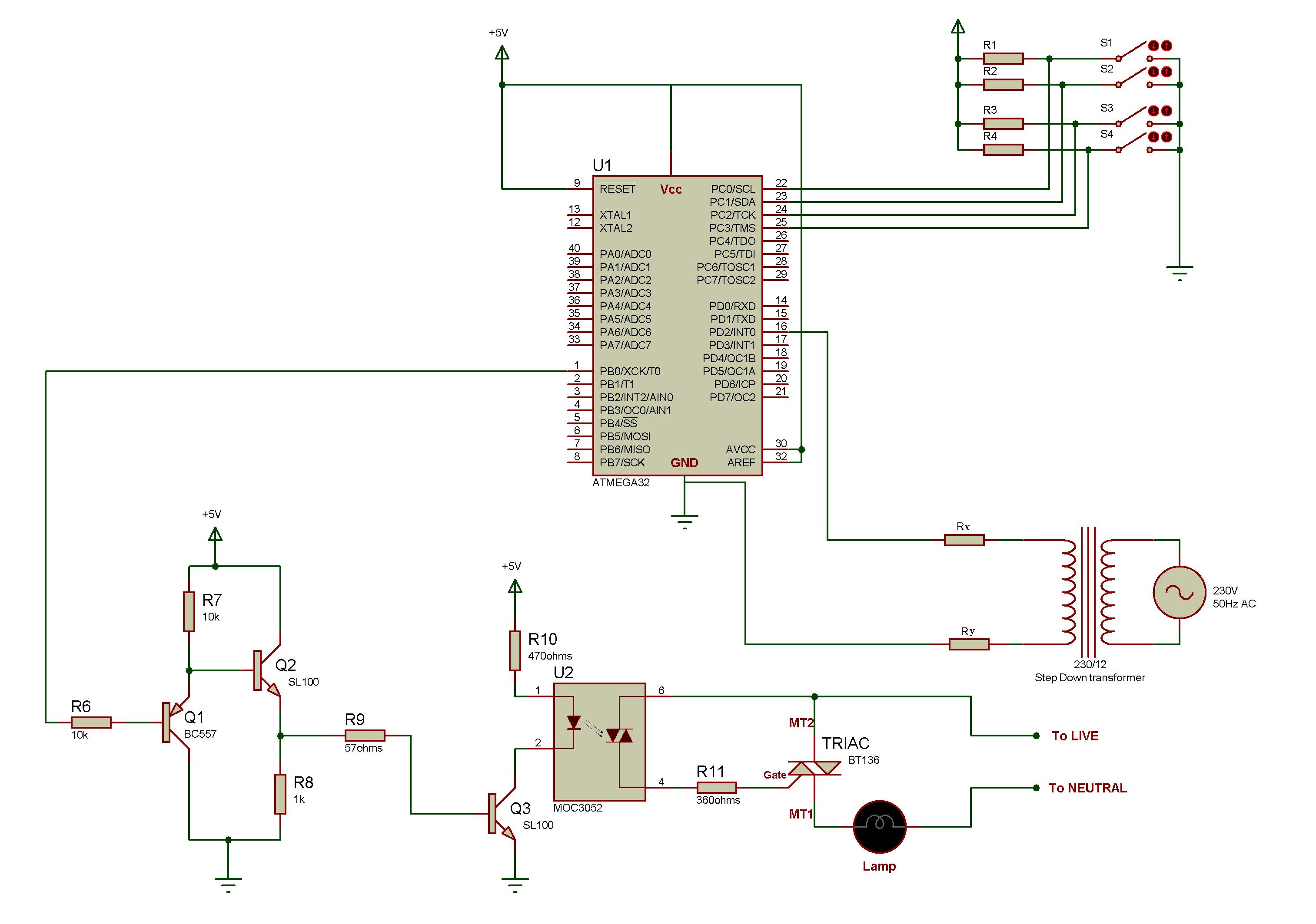
i want to use a similiar circuit for zero crossing as in the atmel apllication.. here i attach a schematic which i want to use ? i also want to add an ac isolator maybe PC814. how do i incorporate it into this schematic ? wat should the value of Ry and Rx be ??


i am using zero crossing to determine the delay in the mcu fter which i trigger the triac

any help will be appreciated
thanks
 

hi,
BTW,wher do you want to put the isolator in that ckt...in between the uC trigger signal and the MOC?
do you really need it as the MOC itself is an opto isolated triac driver
let me know what exactly is your intention.

regards,
 

This circuit appears to apply 12V AC to the AVR input terminals in order to detect the zero crossing. You cannot directly apply 12V AC or about 17V peak to the AVR without damaging it. The circuit uses the limiting resistors RX and RY along with the internal clamp diodes within the AVR to limit the voltage. These internal clamp diodes were not designed to take alot of current. Therefore, I would start by limiting the peak current to less than 500uA.
17V/500uA = 34K ohms. Dividing this equally between RX and RY and choosing the closest 5% resistor means using 18K or greater resistors.
You could use only one resistor(34K or greater) and tie the transformer directly to GND. The original designer apparently used two resistors to limit the current is an unintended mis-connection is made.
For added protection, you could add external Schottky diodes in parallel with the internal clamp diodes, this will take some of the current load off the AVR.
 

i want to use an isolator in the input side .. as the application note says that the zero crossing method may cause noise in enter the digital circuitry .. PC814 could be used in the input side but dunno how..

if i have to use shottky diodes in this circuit how do i do that ?? can u show me the diagram ?
 

use an moc serices opto isolater which has a built in zero crossing detection section and couple it with an SCR.
 

there is a hint in the ckt part..
just hav a look in the attached file.i'm not able to upload the image.
 

Status
Not open for further replies.

Similar threads

Part and Inventory Search

Welcome to EDABoard.com

Sponsor

Back
Top