Neyolight
Full Member level 5
The COM Port works fine when others try to use it on my laptop(with their board and my Serial US Adaptor). I have a feeling my board is messed up or something! Any Serial port troubleshooting tips?
Follow along with the video below to see how to install our site as a web app on your home screen.
Note: This feature may not be available in some browsers.
Have you tried powering down the PICDEM2 Plus, establishing the serial connection via a terminal emulator and then powering the PICDEM2 Plus back up?BigDog
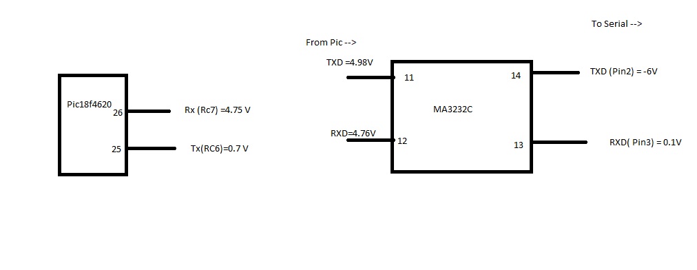
Test the MAXIM RS-232 transceiver chip on your PICDEM 2 PLUS by pulling the PIC18F4620 from the board and shorting the appropriate TX and RX pins of the DIP Socket, then perform the same loopback test from your PC.
BigDog
---------- Post added at 03:53 ---------- Previous post was at 03:49 ----------
I believe you'll need to jumper pins 25 and 26 on the 40-pin socket, to successfully create a loopback.
") I can now "Mark as Solved" this thread
I can now "Mark as Solved" this thread I imported the C file, buit the project and programmed the PIC and the SAME ERROR :|
Maybe I should reinstall MPLAB! It could be corrupt ! What compiler did you use to build it? MPLAB C18 v3.40 is what I used.
What happens if you open the project file of the original project I uploaded? And then try and recompile the project?
BigDog
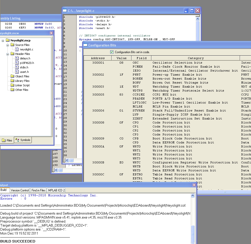
One discrepancy I found between your "confuguration window" and mine is STVREN is set to 01 in yours and 81 in mine. Could the be the culprit- though Im using config in code. Will try setting in the window now...
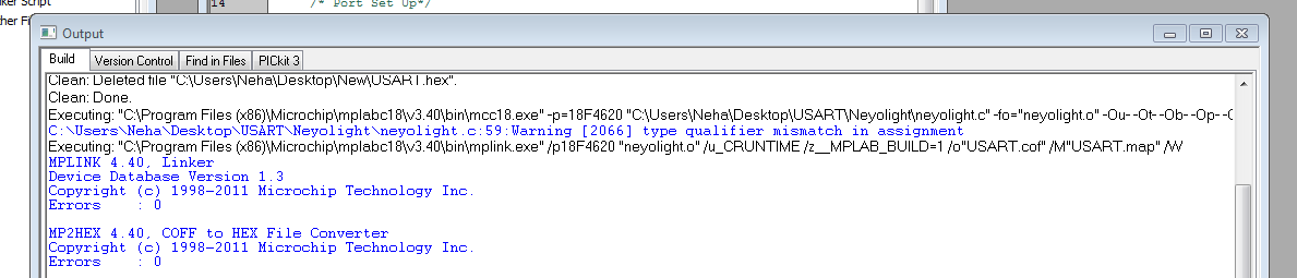
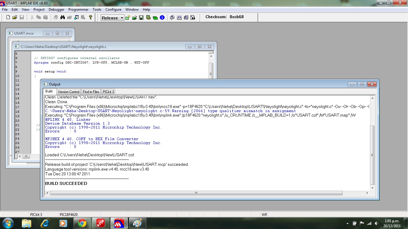
As i just noticed in the above pic, I do have a warning : Warning [2066] type qualifier mismatch in assignment
This if for the line: putrsUSART(" Hello World! ");
Do the LEDs light up as expected?
I suspect the oscillator configuration to be the culprit, which should effect the USART but not the LEDs.
BigDog
#include <p18f4620.h>
#include <delays.h>


// INTIO67 configures internal oscillator
#pragma config OSC=INTIO67, LVP=OFF, MCLRE=ON , WDT=OFF

void setup(void)
{
	/* Clock Setup*/
	OSCCON = 0b01110010; //select 8 MHz clock

	/* Port Set Up*/
	ADCON1 = 0b00001111; //set all pins to digital mode
	TRISD = 0x00;
	TRISA = 0x00;
	TRISB = 0b00000000;
	TRISC = 0b10000000; // RX is an input, TX is output


	/* Interrupt Setup */
	INTCON = 0x00; /* Clear Registers */
	PIR1 = 0x00;
	PIE1 = 0x00;


  // Turn on the 4 LEDs
 // Microchip recommends writing to the PORT Latch rather than the PORT Pins
	LATBbits.LATB0=1;
	LATBbits.LATB1=1;
	LATBbits.LATB2=1;
	LATBbits.LATB3=1;


}


void main(void)
{
	setup();

	while (1)
	{

		Delay10KTCYx(100);

                // Blink the 4 LEDs
               // Microchip recommends writing to the PORT Latch rather than the PORT Pins
	       LATBbits.LATB0 = ~LATBbits.LATB0;
	       LATBbits.LATB1 = ~LATBbits.LATB1;
	       LATBbits.LATB2 = ~LATBbits.LATB2;
	       LATBbits.LATB3 = ~LATBbits.LATB3;


	}
}