Continue to Site

Welcome to EDAboard.com

Welcome to our site! EDAboard.com is an international Electronics Discussion Forum focused on EDA software, circuits, schematics, books, theory, papers, asic, pld, 8051, DSP, Network, RF, Analog Design, PCB, Service Manuals... and a whole lot more! To participate you need to register. Registration is free. Click here to register now.

understanding a relay

Status
Not open for further replies.
Actually Yes, But since the current sources are not readily available, we use the voltage sources........ The rating 12v 5A means the switching is occured at 12V and it can carry 5A of current safely........

Oh. Okay, referring from your circuit version the voltage source connected to NO is 12v 5A. And the supplied amp will differ upon the device being controlled which is the coin box. Did I get that right?:???:

Actually it is ohms law, but instead of R (resistance) you have to use Impedance(z= R+jX where X is the inductive reactance) of the relay coil to calculate the current flows through it.

How do I get the value X?

Thanks for the edited circuit and the link. Now I'm more knowledgeable on this project I'm doing. Thanks sir.
 

Oh. Okay, referring from your circuit version the voltage source connected to NO is 12v 5A. And the supplied amp will differ upon the device being controlled which is the coin box. Did I get that right?

Yes..........And the supplied amp will differ upon the device being controlled which is the coin box...... that is right
But 5A is very large current. So you usually don't require that much current.The 5A providing battery is also costly...... as I said earlier if you want you can go for lower current rating...

How do I get the value X?
Sometimes it will be there in the markings of relay indicating the coil resistance & X ( the reactance). if not you have to calculate it manually or refer the Data sheet for the relay (recommended).....

If you want to calculate manually, you have to place the multimeter accross the coil ends in resistance measuring mode... you will get Resistance........
in a similar way use an inductance meter to know the inductance (L) of the relay..... X =wL , where w =angular frequency)..........

All the best from RJK
 

That is fly back diode ( freewheeling diode ) . if you prevent to use that diode in parallel with your relay , when your transistor is on , we don't have any problem . but when the transistor , wants to be turn off , according to the lenz law (E=L*di/dt) , the inductor of the relay , try to increase the voltage , up to hundreds of volt( at the reverse polarity) . thus that diode can does short circuiting that inductor opposition.and thus can keep your transistor.
Best Wishes
Goldsmith
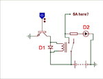
Relay.JPG
Hi Goldsmith,
Look at the attached circuit above. Yes D1 is a Freewheeling Diode and not the D2. I am asking about D2 not D1. D2 has nothing to do with any transient as per the circuit. D1 is in parallel to the relay coil and saves the transistor against any transient (High Voltage) produced by the relay coil while breaking circuit. D2 has no action in the transistor circuit. If you look at the circuit in the post# 14, I have put a RED BOUNDARY on the diode.

Diode suppression of EMF Generated HV Spike
Transient-voltage-suppression diode

Why do they use diodes 4148 in this circuit
kak111, yes you are right and I have no doubts on the using of the Transient Suppressors and I am myself an electronics circuit designer and do use it frequently.

pxkix,
Raza giving some false information?

No I am not giving wrong information. Please read and follow carefully what I said.
 
No I am not giving wrong information. Please read and follow carefully what I said.

No worries. It is just a misunderstanding. Actually D2 is just for an indicator that the relay worked. In the real circuit, it will not exist.

---------- Post added at 19:59 ---------- Previous post was at 19:55 ----------

Yes..........And the supplied amp will differ upon the device being controlled which is the coin box...... that is right
But 5A is very large current. So you usually don't require that much current.The 5A providing battery is also costly...... as I said earlier if you want you can go for lower current rating...

Sometimes it will be there in the markings of relay indicating the coil resistance & X ( the reactance). if not you have to calculate it manually or refer the Data sheet for the relay (recommended).....

If you want to calculate manually, you have to place the multimeter accross the coil ends in resistance measuring mode... you will get Resistance........
in a similar way use an inductance meter to know the inductance (L) of the relay..... X =wL , where w =angular frequency)..........
All the best from RJK

Cool. I understood what you gave me. Thanks a lot.
The battery is just for the software. In actual circuit I'm using a 12v 1A DC adapter.
By the way, is there a way to lower an ampere? Let's say for example I want to use a 12v 10A DC voltage source.

On the relay I have it only says 12v 5A LYNNKS.
 

No I am not giving wrong information. Please read and follow carefully what I said.
You just jumped into conclusions about the function of D2. But nothing has been said or asked about it before. You didn't consider that it may be an intentional load, as it finally turned out.
 

You just jumped into conclusions about the function of D2. But nothing has been said or asked about it before. You didn't consider that it may be an intentional load, as it finally turned out.

In post #14 I just indicated the direction of the Diode. According to the circuit shown it will LOAD battery un-necessarily. So I asked about the usage of this diode, which was responded by many of my colleagues and I got a remark:
Raza giving some false information?
Which I clarified.
Hope any confusion to any one must had been clear now.
 
Last edited:
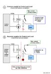
When using relays in control circuits, a great advantage
have been achieved by using a relay as isolator between
the control circuit (eg. MCU) and the load circuit.

Relay_Isolated_Circ_.jpg
 
View attachment 67350
Hi Goldsmith,
Look at the attached circuit above. Yes D1 is a Freewheeling Diode and not the D2. I am asking about D2 not D1. D2 has nothing to do with any transient as per the circuit. D1 is in parallel to the relay coil and saves the transistor against any transient (High Voltage) produced by the relay coil while breaking circuit. D2 has no action in the transistor circuit. If you look at the circuit in the post# 14, I have put a RED BOUNDARY on the diode.

Dear Raza
Hi
Sorry , i thought that you talked about D1 . but about D2 , you're right.
Respect
Goldsmith
 

12V, 5A is just a rating of relay. As Goldsmith told, Relay need 12V to activate the contacts and it's coil can carry current of 5A (maximum).
 

12V, 5A is just a rating of relay. As Goldsmith told, Relay need 12V to activate the contacts and it's coil can carry current of 5A (maximum).
The coil not do not carry 5 amperes (may take a few mA) but the contact's current carrying capacity is 5 amperes in this case.
 

Dear serly
Hi
Where is your post ? the post 14 isn't for you . it is for RAZA .
I saw that at some of the threads you did the behavior like this , can you tell us the reason ?
 

The coil not do not carry 5 amperes (may take a few mA) but the contact's current carrying capacity is 5 amperes in this case.

Ya...its contact's current carrying capacity...sorry for typo....
 

Where is your post ? the post 14 isn't for you . it is for RAZA .
I saw that at some of the threads you did the behavior like this , can you tell us the reason ?
Goldsmith,
I have seen his many posts in the same way. He copies others text in his post and the reader feels it is his post. I think moderators should have a look into this.
 

Are the relays used for :

1) Interfacing low voltage circuit to low voltage circuit

2) Interfacing low voltage circuit to high voltage circuit

3) Interfacing low current circuit to high voltage circuit

4) Interfacing low current circuit to low voltage circuit

5) Interfacing low current circuit to low current circuit

6) Interfacing low current circuit to high current circuit

7) Interfacing high current circuit to low voltage circuit

8) Interfacing high current circuit to high voltage circuit

9) Interfacing high current circuit to low current circuit

10) Interfacing high current circuit to high current circuit

11) Interfacing low voltage circuit to low current circuit

12) Interfacing low voltage circuit to high current circuit

13) Interfacing high voltage circuit to low voltage circuit

14) Interfacing high voltage circuit to high voltage circuit

15) Interfacing high voltage circuit to low current circuit

16) Interfacing high voltage circuit to high current circuit

???
 

Are the relays used for :
1) Interfacing low voltage circuit to low voltage circuit
2) Interfacing low voltage circuit to high voltage circuit
3) Interfacing low current circuit to high voltage circuit
4) Interfacing low current circuit to low voltage circuit
5) Interfacing low current circuit to low current circuit
6) Interfacing low current circuit to high current circuit
7) Interfacing high current circuit to low voltage circuit
8) Interfacing high current circuit to high voltage circuit
9) Interfacing high current circuit to low current circuit
10) Interfacing high current circuit to high current circuit
11) Interfacing low voltage circuit to low current circuit
12) Interfacing low voltage circuit to high current circuit
13) Interfacing high voltage circuit to low voltage circuit
14) Interfacing high voltage circuit to high voltage circuit
15) Interfacing high voltage circuit to low current circuit
16) Interfacing high voltage circuit to high current circuit
???

With that lot of questions it made me confused. Currently I'm using a relay being controlled by a 2222A transistor at the 1st end of the coil and a 12v source at the other end of the coil with a 4001 diode. I'm trying to use the relay to control a solenoid and a wall power source (220v and/or 110v)
 

Dear poxkix
Hi
Your question is simple and has a simple answer , but i can't understand , why , this huge values of replies , and long discussion occurs ?!!!
Relays are just simple devices , that if you give a voltage across it coil , it's contact will change the situation , simply ( on or off ) .
And you can use them simply .
Good luck
Goldsmith
 
  • Like
Reactions: poxkix

    poxkix

    Points: 2
    Helpful Answer Positive Rating
All options (1...16) are possible and are used in different connections and circuits with relays and contactors.
In general, the relay should be understood as a component , where the control circuit generates only a magnetic field in a coil.
This magnetic field is used to generate force that close or open the switch contacts.
Magnetic field is generated by electric current or voltage (V = 3V .... 400V ac or dc) (I = 1mA .... 1000A ac or dc)
in case high current controlled relay voltage can be very low. (Needed power for switch action is UxI)
Contacts can act as switches for voltages and currents. ( V = 1 mV... 2kV ac and dc) ( I = 1mA... 25A ac and dc) ( or in contactors several kiloamperes )
 
Dear poxkix
Hi
Your question is simple and has a simple answer , but i can't understand , why , this huge values of replies , and long discussion occurs ?!!!
Relays are just simple devices , that if you give a voltage across it coil , it's contact will change the situation , simply ( on or off ) .
And you can use them simply .
Good luck
Goldsmith

Thanks. The easiest to understand.

All options (1...16) are possible and are used in different connections and circuits with relays and contactors.
In general, the relay should be understood as a component , where the control circuit generates only a magnetic field in a coil.
This magnetic field is used to generate force that close or open the switch contacts.
Magnetic field is generated by electric current or voltage (V = 3V .... 400V ac or dc) (I = 1mA .... 1000A ac or dc)
in case high current controlled relay voltage can be very low. (Needed power for switch action is UxI)
Contacts can act as switches for voltages and currents. ( V = 1 mV... 2kV ac and dc) ( I = 1mA... 25A ac and dc) ( or in contactors several kiloamperes )

Does a relay when activated disrupts the controlling circuit? I'm using relays (for me) a difficult circuit, whenever any of the relays are triggered the whole circuit goes kaput. I really don't know why. The relay is used to control a 12v solenoid lock. It is four different solenoid locks.
qweqwe.png
 

whenever any of the relays are triggered the whole circuit goes kaput. I really don't know why.

I guess, it's not a problem of understanding relays as such. Your schematic looks fine so far. Assuming the power supply is able to source the relay coil current, it's most likely a problem of contact arcing and electrical interferences affecting the controlling circuit, e.g a microprocessor.

The problem can refer to an unsuitable design of both parts, controlling and power circuit. You can design the controlling circuit in a way, that it's almost immune against strong interferences, e.g. sparks discharging near to the processor. And you can suppress contact arcing effectively by snubbers, varistors or voltage suppressor diodes, so even sensitive circuits won't be disturbed by it.
 

Your schematic is OK.
Check that your circuit is connected as drawn in schematic.
( Diode cathode to plus)
(Check, have your relays fixed transient diodes and now connected wrong)
Relay coils are for 12Vdc
Is your 12V power capable to supply lock solenoids.
( Do check without solenoids)

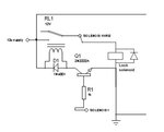
When relay contact opens, lock solenoid inductance create high voltage transient over relay contacts.
Use diodes to kill that spike same way as done with relay coils.

Lock_Solenoid_01.jpg
 
Last edited:
Status
Not open for further replies.

Part and Inventory Search

Welcome to EDABoard.com

Sponsor

Back
Top