Continue to Site

Welcome to EDAboard.com

Welcome to our site! EDAboard.com is an international Electronics Discussion Forum focused on EDA software, circuits, schematics, books, theory, papers, asic, pld, 8051, DSP, Network, RF, Analog Design, PCB, Service Manuals... and a whole lot more! To participate you need to register. Registration is free. Click here to register now.

Ultrasonik sensör

Status
Not open for further replies.

aknalemdar

Newbie level 6
Joined
Sep 2, 2021
Messages
13
Helped
0
Reputation
0
Reaction score
0
Trophy points
1
Activity points
108
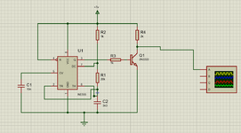
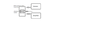
I have a 48 kHz receiver and transmitter ultrasonic sensor. I'm trying to build a circuit with these to detect thin objects as thick as paper. I tried to set up an oscillator circuit to drive these sensors. But I was not very successful. I would be glad if you help.
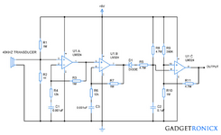
 

Attachments

  • 1.png
    1.png
    67.1 KB · Views: 108
  • 2.png
    2.png
    31.4 KB · Views: 112

Hi,

Forum rules say:

Only you know what "doesn't work" means
Please tell us what your circuit or code is supposed to do and why it "doesn't work".When you come in and say "it doesn't work" or just "it has errors", that means NOTHING. There could be a million things wrong and no one will know where to look.


Could you please explain what "was not successful" means?

Klaus
 
The problem is. I connected my receiver circuit. The project I want to do is as follows: There will be a receiver and a transmitter. I will position them facing each other. And the distance between them will be 0.1 inch. When I pass a piece of paper between this distance, I aim to decrease the voltage I get from the output and program it with a microcontroller. Actually, this is a school project. The problem I'm stuck with is that I want to do this process in a serial way, but the frequencies in the circuit I created are very active, even though I program them as in the picture, I cannot determine the frequency range because it is very variable. For example, I need to make him understand that the paper passes at x tension and is empty at y voltage. My goal is a high efficiency frequency generator and output circuit that will convert this frequency to voltage nicely.
 

Attachments

  • ultrasonic-receiver-circuit.png
    ultrasonic-receiver-circuit.png
    32.6 KB · Views: 104

Hi,

without a sketch .. I don´t understand.

What I see in the circuit:
* it has 40kHz input (no info about waveform, so sine, hopefully)
* then there are two amplifiers with gain of 80 in series.
* 40kHz x 80 = 3.2MHz
* but LM324 has a GBW of 1MHz only. --> LM324 is way too slow. It can´t work.

I recommend an OPAMP with GBW of at least 32MHz.

*****

You say:
and output circuit that will convert this frequency to voltage nicely.
I don´t think you want a frequency-to-voltage converter.
What I see is a (negative) peak detector.

For this I´d use R5 much lower, maybe 4k7.

****
You need a scope to trace the signal from generator to to tx, Rx, amplifier, peak detector.

Klaus
 
I agree that the lousy old LM324 quad opamp is way too slow for ultrasonics. It is not even used for audio.

The datasheet for an LM324 shows that it works poorly at frequencies above a few kHz.
If you used a modern audio opamp then the first two opamp voltage gains total would be 7112 times. The total of the voltage gains of an LM324 opamp would me MUCH less at 40kHz but would be the same at 3kHz, the highest frequency of an old telephone.
 
Hi,

Does the receiver thing ideally output a 9V signal or is it a signal in the range of millivolts? I've never used one so I have no idea.

Does the NPN need to output 3.5mA, is that why the 2k? You could maybe change the 2N2222's base resistor to 10k or even 22k. It wouldn't hurt to put a pull-down resistor between the base resistor and the BJT base, either, e.g. 220k; I'm a big fan of 1M as a pull-down, no doubt other people aren't.

Have you measured or 'scoped the 2N2222's output voltage levels, and if lucky and have a 'scope, its signal still looks like the 555s 'square wave'? Does the 555 output a decent square wave?

What frequency is variable? If you mean the 555 output, that's life... The 555 is not very accurate for timing. If needs must be using a 555, a way to ameliorate this is by increasing your timing resistors by an order of magnitude and scaling down the capacitor in the opposite direction (10k, 200k, 330pF). Also, use a capacitor that is described as for timing applications like NPO or go opulent and try PPS or polystyrene; X7R and worse dielectrics are not good in timing applications, PET (MKT) are sort of okay but I'd really take care of the timing capacitor dielectric selection and be fussy there as the capacitor choice ruins or makes tolerable everything where timing is concerned.

Bad suggestion, perhaps (and this is a quick sketch of an idea, not a complete blueprint/turnkey project): if the 40kHz or 48kHz or whichever frequency it is transducer outputs a several-volt-sized signal (not millivolts or something tiny), its output signal could be fed into a fast diode like the 1N4148 and from there into an RC network, to rectify and smooth the ripple, and compare that undulating or ideally smooth voltage to a comparator (with a lot of hysteresis I guess would be needed) with a voltage reference. That way you could make Klaus (really) angry ( ;) )and use the slow LM324 as a comparator. Experimentation or maths would show what rectified voltage to expect for the voltage reference. Maybe it's another approach, but I haven't thought about it much so it might be a very bad idea.
 
A typical 40 kHz transducer has a usable bandwidth of a few 100 Hz up to 1 kHz maximal. Respectively the frequency of the RC oscillator must be adjusted. The single ended driver transistor with 2k load resistor is not helpful, the transducer can be better driven by 555 output directly, it's low impedance push-pull.

I agree that LM324 isn't well suited as AC amplifier, due to class B output stage and low GBW. I would at least use a 4 MHz GBW general purpose OP. I presume you don't need high gain for 0.1" sensor distance.
 
I played with a pair of ultrasonic transducers, 38 kHz. They appear to be interchangeable as sender and receiver. The frequency range is narrow. I agree you need to adjust frequency so you can find the strongest response.

Your separation distance 0.1 inch is reasonable to create a difference in signal strength when paper passes between.
 
A typical 40 kHz transducer has a usable bandwidth of a few 100 Hz up to 1 kHz maximal. Respectively the frequency of the RC oscillator must be adjusted. The single ended driver transistor with 2k load resistor is not helpful, the transducer can be better driven by 555 output directly, it's low impedance push-pull.

I agree that LM324 isn't well suited as AC amplifier, due to class B output stage and low GBW. I would at least use a 4 MHz GBW general purpose OP. I presume you don't need high gain for 0.1" sensor distance.
I understand what you said. So, is this frequency value enough at a distance of 0.1 inches? Can this be done with 40 kHz? If I pass 100 pieces of paper per second in front of this sensor, can it detect these pieces one by one?
 

Hi,

fast sheets of paper detection.
Why ultrasonic? Why not with optical sensors?

Klaus
 
Hi,

fast sheets of paper detection.
Why ultrasonic? Why not with optical sensors?

Klaus
You are right, but my thesis is on ultrasonic. I also thought that this process can be done with ultrasonic sensors. Do you think it can be done?
 

Hi
If I pass 100 pieces of paper per second in front of this sensor, can it detect these pieces one by one?
difficult.

lets say the space between the papers are exactly as long as the length of the paper
(this is best case for 50% paper and 50% space, means 50% ON signal and 50% OFF signal)
then you have 5ms paper and 5ms space.

within these 5ms you have 200 fullwaves of the 40kHz signal.

So your pulse detecting filters have to be fast enough.

--> I´d go with a "Lock in amplifier" (LIA). Here you get very good signal-to-noise and you are flexible with filtering, since the ON/OFF delay is symmetric.

****
0.1" means about 8.5us "time of flight"... and a phase shift of 120 degree.

The paper may cause amplitude modification, but also phase shift modification.
With a LIA you are able to detect both.

***
a rather advanced solution could be:
* PLL to generate (adjustable) frequency for ultrasonic transducer as well as LIA control
* a filter to generate an almost sine shape transducer signal
* some analog switches (digitally controlled by PLL signal) as LIA
* some analog filters for the LIA output(s)
* Comparators or ADC and microcontroller as paper / no_paper detector.

for sure more simple solutions are possible, too.

Klaus
 
What does LIA mean?

I want to ask one more thing. Can I connect the transmitter sensor directly to my frequency generating oscillator circuit as seen in the photo above? Do I need a driver circuit separately? Thanks.
 

Why you need so much power? A couple of mW output power should be sufficient.

So do these things in a systematic way. Put the transmitter in the feedback loop and set it oscillate at its natural frequency. You should get sufficient power to detect both reflection and transmission over several meters.

Next set up your received as a simple microphone with a bandpass filter at the input. What is the rated power of the transmitter?

What circuit you are using as the freq generation?
--- Updated ---

I understand what you said. So, is this frequency value enough at a distance of 0.1 inches? Can this be done with 40 kHz? If I pass 100 pieces of paper per second in front of this sensor, can it detect these pieces one by one?
1. Freq must be matched with the transmitter module. It has nothing to do with distance.

2. Yes, it can be done at 40 kHz, It can be done at 20 kHz too! You are just measuring the attenuation of the signal seen at the detector level.

3. If you pass 100 sheets of A4 pages in one second, that is 10 ms per page, with a gap between the pages equal to more than a couple of inches (more than 10% of the paper length), yes, you can do that without error.
 
Last edited:
Hi,
What does LIA mean?
It´s already explained in my text.

I want to ask one more thing. Can I connect the transmitter sensor directly to my frequency generating oscillator circuit as seen in the photo above? Do I need a driver circuit separately? Thanks.
It depends on the driving capabilities of the oscillator and the current drawn by the sensor.
You need to read both datasheets.

Can you lift a stone? It depends on how strong you are and the weight of the stone.

Klaus
 
I already suggested to drive the transmitter by 555 directly, that's at least better than your circuit. 40kHz sensors have typical impedance of 500 ohm to 1k in resonance. Can be driven by 555.
The response time can be reduced by loading the receiver resistively, at cost of lower output voltage. A value below 1 ms should be feasible.

Before designing specific detector circuits, e.g. suggested synchronous detector, I would watch the received signal with an oscilloscope.
 
Thank you all. As far as I understand, I will drive the transmitter sensor with the 555 integrated. And I will fine-tune the signal converter circuit in the receiver sensor. I will make these games to get suitable gain values according to frequency. Actually, I will design this circuit and share the necessary test data with you here. I want to stay in touch with all of you. Thank you so much.
 

Thank you all. As far as I understand, I will drive the transmitter sensor with the 555 integrated. And I will fine-tune the signal converter circuit in the receiver sensor. I will make these games to get suitable gain values according to frequency. Actually, I will design this circuit and share the necessary test data with you here. I want to stay in touch with all of you. Thank you so much.
I guess you will be using the 555 with the 2N2222 driver. That is fine, you can put the oscillator on the collector of the 2N2222.

Also replace R1 with a fixed resistor and a trimpot. You can tune the freq with the trimpot. Do some calculation first.

Also put a 100 ohm resistor in series with the transmitter. You measure the voltage when you tune the frequency. When you get the max voltage, that is your optimum.

You can tune the receiver the same way.

Good luck!
 
I agree with FvM in post #7 where it says that the transistor is not useful, a direct connection to the 555 output is much more powerful (200mA is available) than the transistor with its puny 3.5mA from the 2k resistor.

I think the ultrasonic transmitter transducer is piezo which is like a capacitor that has a membrane that flexes when a voltage is applied. Then it works much better when AC is applied so it can flex back and forth instead of the DC pulses from the transistor or from the 555 which cause the flexing in only one direction. AC can be made from a circuit that uses a plus and minus power supply or it can be made with a single power supply polarity if a bridge circuit drives each of the two transducer wires. A second 555 or a dual 556 can be used as a bridge to drive both transducer wires with AC.

Have you selected the ultrasonic transducers? Please attach their datasheet.
 
These are my sensors. The reason I chose these sensors is the wide-angle frequency distribution. That's what I thought, since the sensors would be so close together. If you have any ideas, I'm open to it. For now, I am determined to drive the transmitter with the 555. But I'm undecided on how to convert the frequency of my receiver sensor to voltage. I'm having trouble setting up the circuit on the receiver part. Respects.
 
Last edited by a moderator:

Status
Not open for further replies.

Similar threads

Part and Inventory Search

Welcome to EDABoard.com

Sponsor

Back
Top