Continue to Site

Welcome to EDAboard.com

Welcome to our site! EDAboard.com is an international Electronics Discussion Forum focused on EDA software, circuits, schematics, books, theory, papers, asic, pld, 8051, DSP, Network, RF, Analog Design, PCB, Service Manuals... and a whole lot more! To participate you need to register. Registration is free. Click here to register now.

Uart Communication to Multiple Slaves

Status
Not open for further replies.

gauravkothari23

Advanced Member level 2
Joined
Mar 21, 2015
Messages
640
Helped
5
Reputation
10
Reaction score
4
Trophy points
1,298
Activity points
6,922
Hi all.
I am trying to communicate on Uart on MS51FB9AE controller. the baud rate i am using is 1200
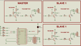
have also attached the circuit diagram. In circuit diagram, i have defined two slaves and 1 master and communication circuit using transistors.
the Communication is some thing like i have a button on the board and LED on both master and slave PCB's. when button is pressed from slave, master LED glows for 1 second and goes OFF. and again when the button is pressed from master once, the 1st slave LED will glow ON, and when 2nd time the button is pressed, the second slave LED will glow and so on. Total i have connected 15 slaves and 1 master. The slave have individual address which i have defined using J13 Connector.
The communication is done at the distance of approx 10 Metres using 4 core wires. The system is powered using 24V DC power supply and then 7805 which is not shown in the circuit.
My problem is when single slave in connected to master, it works well, but when 2 or more slave is connected, most of the times when the button is pressed from any slaves, master LED does not glow, but in the same case, when 15 slaves are connected, and button is pressed from master, the slave LED's glow properly,
so, i am facing a problem in data transmission from slave to master. but from master to slave works well. i even tried using Opto coupler PC817 instead of transistors, but still the same problem.
can anyone please suggest me any solution for this.
 

Attachments

  • Uart.png
    Uart.png
    34.4 KB · Views: 292

It's not clear how this is all connected. Are you trying to do a wired-OR? Do you have all the slave transmits tied together? and all the slave receives? If so, you should have just one pullup, not 15.

Have you looked at your signals?
 

Hi,

Similar projects are done thousands times before. Did you check some of them?

Hardware:
* I don't see where the Tx fro the master goes to the Tx of the slaves ... and vice versa.
* I don't see pullups in Tx and Rx
* I don't understand how this can work when standard UARTs are idle_high.
* I don't see how you treat ambient noise, like when the refrigerator nearby switches ON/OFF
* I don't know what communication protocol you use, how you avoid collisions...

The headline talks about UART communication, but then I get confused by buttons, LEDs, 24V and so on ... I don't understand how all this is related.

Klaus
 

Remove all the receiver base pull-up resistors completely. (R4, R23, R27 etc)
Add one resistor (about 1K) on the line marked RX to the supply to pull it up.

Your software will have to ensure only one slave output is pulled low at a time.

Brian.
 

It's not clear how this is all connected. Are you trying to do a wired-OR? Do you have all the slave transmits tied together? and all the slave receives? If so, you should have just one pullup, not 15.

Have you looked at your signals?
Yes I have all the slaves TX connected together with Master RX and slaves RX connected together with Master TX.
Sorry, but I forgot to mention that Only Master PCB is powered using 24V power supply. And the same is carry forward using wires to slave 1 and then slave 2 and so on.
So at slave 15 I am getting a voltage drop of approx 1.3V.
 

Hi,,

24V --> 7805 --> 5V
Means you have to dissipate the 19V as heat. Your power supply needs to provide about 5 times the power than necessary.
Why 24V? 12V should easily do (half the power than befire)
But I'd use those tiny DC/DC converters instead of the 7805, then you dissipate just a tiny amount of power while it does not matter whether you use 12V or 24V input (with about 1/5 the size than before).

***
Using a single pullup at one "base" won't give save voltage levels to drive all other Rx BJTs. Ground bounce (1.3V/2) across the bus line makes save levels imposible. No noise margin. (Btw: using the 24V DCDC system: reduces the bus GND current --> reduces voltage drop --> increases noise margin.)

In the past decades others have made similar designs, with similar problems ... thus they already found out how to make such single signaling "multidrop buses" ... and they found out the benefits of differential signaling.

These single signal lengthy busses have several problems:
* noise pickup
* ground bounce
* usually no clean characteristic impedance system --> causing echoes and ringing

In your case several problems are combined.
* the bus voltage levels (I mentioned earlier)
* the ringing
Mind: it does not matther whether you use 1kBaud or 100kBaud ... the ringing at the edges is the same.
If you want to reduce ringing, then you need to reduce the driver's slew rate. (Thus there are RS232 drivers as well as RS485/RS488 drivers with reduced slew rate). And the reduced slew rate is the reason why you can't ransmit higher baud rates.

To reduce the effect of noise and ringing you may use a simple filter at the receivers and use schmitt trigger inputs to get clean noise margins.

****
If I had to do the same:
* for a reliable (industrial) design: I'd use RS485/RS488 with true characteristic impedance wiring.
* for a cheap DIY system: single wiring multidrop design. Idle high for "wired AND" structure, a small capacitor from colletor to base at the drivers to reduce slew rate, an RC (to suppress refrigerator noise for example) and double ESD diodes to a schmitt trigger input at each receiver, a protocol to detect errors (at least a CRC).

Re-inventing the wheel:
Doing it your own way, finding out problems, solving problems is the best way to teach onself. All the informations will be manifested in your brain for the future. I recommend to look at scope videos of bus signal voltages at the driver and several slaves close to the driver and far away from the driver to keep that pictures in your mind. This will result in a great learning curve.

On the other hand if you want to speed up design by avoiding mistakes I recommend an internet research before.
****

Sorry for the lengthy post, but I wanted to mention all the most important topics at once.
And: no pressure ... the above is just my way ... no need for you to do it the same way.

Klaus
 
Klaus makes many valid points: You will definitely learn something with this bad design (History is a wonderful teacher; it enables us to recognize a mistake when we make it again); RS-422/485 is a much better way to accomplish what you’re trying to do.

Also, a voltage drop of 1.3 volts is ENORMOUS. 24 AWG wire, for example, has less than 1 ohm of resistance for 10 meters.That would imply you’re drawing well over an amp.

But I’m sure with enough fiddling and modification you could get your existing desIgn to work. Is it worth it?
 

Yes, I agree with you all.
I think the only way to make it possible and last longer and easy is to use RS232. will surely implement it.
 

Hi,

No, no , no .. RS232 isn´t a good solution, because it usually isn´t able to disable drivers. It´s just made for two partners, it´s not a bus for multiple partners.

You may stay with a 5V level multidrop bus.
or you may go with a differential bus. If you want to save line count then use a bidirectional RS485 system.

I really recommend to do a search for similar projects. I guess you will find a lot of suitable solutions.

Klaus
 

Status
Not open for further replies.

Similar threads

Part and Inventory Search

Welcome to EDABoard.com

Sponsor

Back
Top