cupoftea
Advanced Member level 5
Hi,
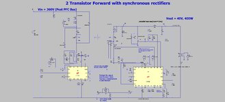
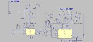
I am trying to get a 2 transistor forward working with the LTC3765/LTC3766 combo, in LTspice.
(I have high voltage reset so max duty can be >50%)
The LTspice simulation of this combo runs almost insanely slowly on my 8GB Laptop. (Huawei Matebook D)
The LTC3766 datasheet says max duty cycle is 80%. The LTC3765 says the max duty is 70%. So I presume it will be 70% max.(?).
Also, there is a “ripple rejection” feature with this chipset. This seems to be a means of keeping the output current clamped to a certain, chosen level when the output is overloaded. I have simply disabled this for this simulation.
There is a feature for inferring the magnetising current ramp on the forward stroke….however, I have disabled this since I simply have a 1100V reset voltage so that magnetising current always resets.
There is also a v.us clamp pin (VSEC pin), but I have disabled this too.
There is also a facility to sense current in the synchronous FET (I call it the freewheel FET). But again I have disabled this.
>>>
Anyway, I am noticing that at certain times of the simulation, the “synchronous” FET is staying on for longer than a switching period…this surely should never be allowed?
Also, there are huge switching current spikes in the synchronous FETs…and this cannot be resolved no matter how the delay resistors are adjusted.
Also, the sec side forward synch fet comes on before the primary FET…and this should surely never happen?.....surely the sec side forward synch fet should only cone on after its diode has started conducting?
Do you have any way of righting this sim?.....even any way of speeding it up?…it is ridiculously slow.
>>>
Also, the primary FET has the usual source sense resistor. However, in this case, if ever the primary current hits the current sense threshold (150mV), then the converter goes into fault, shuts down, then hiccups back ON. As you know, this is a very poor way to do things. As the LTC3765 datasheet explains, the soft start capacitor must be correctly set so that the source current sense threshold never gets breached at start up. (or else it wont start up!). But what about no_load_to_full_load transient, when the soft start capacitor is fully charged?……..i suppose its just tough…..the converter will go into endless hiccupping……quite something when you’ve payed >£12 for the LTC3765/LTC3766 combo.
>>>
Originally, we were hoping to use this chip, with some extra circuitry, to do an offline synchronous two transistor forward converter. However, due to the modus operandi of these chips, this simply wont be possible. So it continues, there is no bona-fide chip or chipset on the market today, for doing a bona fide offline synchronous two transistor forward converter.
>>>
Not only that, but >£12 for a chipset that doesnt even bother to limit the "synchronous " FET on time to less than the switchind period??? (in certain situations).
I am trying to get a 2 transistor forward working with the LTC3765/LTC3766 combo, in LTspice.
(I have high voltage reset so max duty can be >50%)
The LTspice simulation of this combo runs almost insanely slowly on my 8GB Laptop. (Huawei Matebook D)
The LTC3766 datasheet says max duty cycle is 80%. The LTC3765 says the max duty is 70%. So I presume it will be 70% max.(?).
Also, there is a “ripple rejection” feature with this chipset. This seems to be a means of keeping the output current clamped to a certain, chosen level when the output is overloaded. I have simply disabled this for this simulation.
There is a feature for inferring the magnetising current ramp on the forward stroke….however, I have disabled this since I simply have a 1100V reset voltage so that magnetising current always resets.
There is also a v.us clamp pin (VSEC pin), but I have disabled this too.
There is also a facility to sense current in the synchronous FET (I call it the freewheel FET). But again I have disabled this.
>>>
Anyway, I am noticing that at certain times of the simulation, the “synchronous” FET is staying on for longer than a switching period…this surely should never be allowed?
Also, there are huge switching current spikes in the synchronous FETs…and this cannot be resolved no matter how the delay resistors are adjusted.
Also, the sec side forward synch fet comes on before the primary FET…and this should surely never happen?.....surely the sec side forward synch fet should only cone on after its diode has started conducting?
Do you have any way of righting this sim?.....even any way of speeding it up?…it is ridiculously slow.
--- Updated ---
>>>
Also, the primary FET has the usual source sense resistor. However, in this case, if ever the primary current hits the current sense threshold (150mV), then the converter goes into fault, shuts down, then hiccups back ON. As you know, this is a very poor way to do things. As the LTC3765 datasheet explains, the soft start capacitor must be correctly set so that the source current sense threshold never gets breached at start up. (or else it wont start up!). But what about no_load_to_full_load transient, when the soft start capacitor is fully charged?……..i suppose its just tough…..the converter will go into endless hiccupping……quite something when you’ve payed >£12 for the LTC3765/LTC3766 combo.
--- Updated ---
>>>
Originally, we were hoping to use this chip, with some extra circuitry, to do an offline synchronous two transistor forward converter. However, due to the modus operandi of these chips, this simply wont be possible. So it continues, there is no bona-fide chip or chipset on the market today, for doing a bona fide offline synchronous two transistor forward converter.
--- Updated ---
>>>
Not only that, but >£12 for a chipset that doesnt even bother to limit the "synchronous " FET on time to less than the switchind period??? (in certain situations).
Attachments
Last edited: