Continue to Site

Welcome to EDAboard.com

Welcome to our site! EDAboard.com is an international Electronics Discussion Forum focused on EDA software, circuits, schematics, books, theory, papers, asic, pld, 8051, DSP, Network, RF, Analog Design, PCB, Service Manuals... and a whole lot more! To participate you need to register. Registration is free. Click here to register now.

Tv chroma delay line digital interface

Status
Not open for further replies.

dr pepper

Advanced Member level 1
Joined
Mar 15, 2010
Messages
420
Helped
34
Reputation
68
Reaction score
40
Trophy points
1,308
Location
lancs
Activity points
4,128
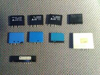
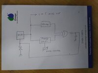
I want to interface a Tv acoustic delay line to digital cmos ic's, so I can play with the idea of using the delay line as a simple huff puff frequency stabiliser.
I'm guessing impedance is going to be important, should I chuck together a bridge to measure it?, my van doesnt go that low.
I know this is a silly idea and there are many better ways, its something I've wanted to play with for a while.
 

Chroma delay line is working at chroma carrier (4.43 +/- 1 MHz), it should be supported by most network analyzers. You should be nevertheless able to find the nominal impedance by looking into application schematics.
--- Updated ---

Many PAL delay lines have impedance of 150 ohm.
 
Last edited:

Ok, I had it in mind it carried a horizontal line or 64uS, wrong again.
I'll connect it to my nano, 150 ohm at 4.43 mc is well within its grasp.
Some cmos devices have lower imp's than 150r so at least on the i/p a couple of passives would work as an interface.
--- Updated ---

Ok I get it now, the transducers operate at 4.43mc, but the delay time is 64uS.
So to get a 64uS delay I could use a tone burst from a transistor osc with a colourburst xtal, and some form of carrier detect at the other end.
 
Last edited:

I wouldn't expect particularly good temperature stability, in their normal usage, minor changes in delay are acceptable.

A caution: there are different types of chroma delay line, you mention acoustic so I assume you mean a glass type but beware that in some TVs, particularly some Asian models, an unusual decoding principle was used that used different delays. They were easy to spot because the chroma decoder used two crystals with frequencies 7.8KHz apart. There are also delays used only to delay the luminance signals by just a few uS to align it with the chroma which took longer to pass through the narrower bandwidth of its processing circuits.

Brian.
 

My selection of delay lines.
I have no idea what kind of Tv or decoder system they use.
However I'm sure some time with a sig gen and my Vna will tell me more about them.
I also have a huge block of quartz from a tube Tv too somewhere.
I'm not expecting ultimate accuracy, but I will compare it to my Hp Gps reference.
 

Attachments

  • IMG_20220421_201632.jpg
    IMG_20220421_201632.jpg
    4.2 MB · Views: 116

Connecting a 100r resistor in series with the vco output of a 4046 Pll to the input of the delay line, and a simple low input impedance transistor amp on the output of the delay line interfaces the line acceptably well to the hcmos.
The idea is to use the delay line to stabilise the 4046's vco, so the next step would be to make a variable phase shift network, with the delay line being fixed I need to adjust the phase shift to shift the filtered output voltage from the comparator to control the frequency of the vco.
 

I'm not clear about what you are trying to do. The filtered voltage from the comparator will be DC if you have stabilized the frequency so phase shifting it makes no sense. Can you show a schematic or at least a block diagram of how you propose to connect things.

Brian.
 

Ok heres a rough drawing, I dont know if the idea will work or not, Dll's are not my thing.
The voltage controlled osc is controlled by the phase comparator, after comparing the phase from the delay line and the adjustable all pass filter, kinda like a Dll that uses a variable delay but the other way round, the result being a variable frequency oscillator that is stabilised by the delay lines accuracy.
If the idea has a chance of working would the all pass be tuned to phase shift the 64uS of the delay line and be wide enough band for the range of the o/p frequency?
 

Attachments

  • IMG_20220425_143953.jpg
    IMG_20220425_143953.jpg
    2.9 MB · Views: 128

64us Delay is valid around 4.43 MHz Chroma Carrier only. The bandwidth will be approx. \[ \pm 1.4MHz \]
for PAL-BG system.
 

A mate of mine over in spain told me the braun se402 has a Vfo with a Tv delay line in it.
I found the schem of the Braun on radiomuseum, pretty much the same as my block dia.
I think I get the principle, the loop controls the time of the 2 signals, which results in a variable voltage when adjusting the phase shift network, and then this controls the Vfo, the stability of the output is as good as the stability of the delay line.
 

Status
Not open for further replies.

Part and Inventory Search

Welcome to EDABoard.com

Sponsor

Back
Top