OZZAA
Member level 1
Dear All,
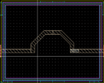
I want to mimic the layout TSMC 0.18um technology's Inductor to get approximately the same results using ADS Momentum tool at 10 GHz.
Where it consists of M6 (Blue wire) and M1(Green wire), with the same dimentions of the original TSMS inductor at cadence layout.

there is a signifiacntly difference between the results of the TSMC saved data at ADS and the data extracted using Momentum as follows:
Firstly: I built the following circuit the L and Q at 10 GHz were 226 pH and 18, respectively

Secondly, I used the extracted Em model from the layout of the ADS
when I used 3 single ports (input port was in the left of the M6 wire, Output port was in the right of the M6 wire, and the 3rd port was connected to the M1 wire (GND port)
the L and Q were 135.7 pH (significantly decrese) and 14.1 (Little change, and accepted), respectively.
When I used 2 diffrential ports, the 1st one was at left and was attached between M6 and M1 wire, the other was at the right and also was attached between M6 and M1 as follows

the L and Q were 209.6 pH (little change, and accepted ) and 2.8 (big change), respectively.
Any advice to know why there was a big difference between the results or did I assign the ports improperly?
Thanks in advance
I want to mimic the layout TSMC 0.18um technology's Inductor to get approximately the same results using ADS Momentum tool at 10 GHz.
Where it consists of M6 (Blue wire) and M1(Green wire), with the same dimentions of the original TSMS inductor at cadence layout.
there is a signifiacntly difference between the results of the TSMC saved data at ADS and the data extracted using Momentum as follows:
Firstly: I built the following circuit the L and Q at 10 GHz were 226 pH and 18, respectively
Secondly, I used the extracted Em model from the layout of the ADS
when I used 3 single ports (input port was in the left of the M6 wire, Output port was in the right of the M6 wire, and the 3rd port was connected to the M1 wire (GND port)
the L and Q were 135.7 pH (significantly decrese) and 14.1 (Little change, and accepted), respectively.
When I used 2 diffrential ports, the 1st one was at left and was attached between M6 and M1 wire, the other was at the right and also was attached between M6 and M1 as follows
the L and Q were 209.6 pH (little change, and accepted ) and 2.8 (big change), respectively.
Any advice to know why there was a big difference between the results or did I assign the ports improperly?
Thanks in advance