Continue to Site

Welcome to EDAboard.com

Welcome to our site! EDAboard.com is an international Electronics Discussion Forum focused on EDA software, circuits, schematics, books, theory, papers, asic, pld, 8051, DSP, Network, RF, Analog Design, PCB, Service Manuals... and a whole lot more! To participate you need to register. Registration is free. Click here to register now.

Triple insulated wire preferred for 50:1 Current sense transformer secondary

Status
Not open for further replies.

cupoftea

Advanced Member level 5
Joined
Jun 13, 2021
Messages
2,636
Helped
54
Reputation
108
Reaction score
116
Trophy points
63
Activity points
13,826
Hi,
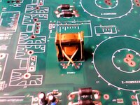
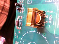
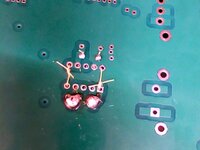
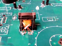
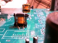
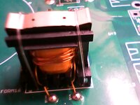
Doing 50:1 Current sense transformer for UCC28070A Boost PFC. Each Booster is 1kW. For secondary, choice is between 50 turns of TEX-E 0.2mm, or 50 turns of 0.4mm Enamelled copper wire. Both are pretty much same in outer diameter.

Would you agree that the TEX-E is preferable, since with the insulator jacket around it, the interwinding capacitance will be less, and the reset of the CST will be more effective?
In UCC28070A Boost PFC, the CST is set up in unidirectional mode. (The CST is in series with the drain of the FET, and incidentally, the “downstroke” is estimated by the UCC28070A)

TEX-E triple insulated wire.
https://www.furukawa.co.jp/tex-e/en/product/texe_series.html

UCC28070A
 

Also, please could i ask if the attached images show adequate coupling between pri and sec of the CST? Pri is TEX-ELZ 7/0.3mm and sec is 50 x TEX-E 0.2mm.

Also, the TEX-ELZ 7/0.3mm is said to be solderable, but trying to solder the ends to the PTH pads was less than easy (as pic shows)...also difficult to be sure that all the Enamelled strands have been soldered. Do you have a better way?
 

Attachments

  • cst1.jpg
    cst1.jpg
    110.9 KB · Views: 81
  • cst2.jpg
    cst2.jpg
    89.8 KB · Views: 85
  • cst3.jpg
    cst3.jpg
    83.6 KB · Views: 85
  • cst4.jpg
    cst4.jpg
    108.2 KB · Views: 98
  • CST UnderPCB.jpg
    CST UnderPCB.jpg
    68.6 KB · Views: 93
Last edited:

Hard to say without seeing a schematic showing where the CST is located in the circuit and the applied voltage/current.

I highly doubt there's any benefit to using litz wire here.
 
Thanks, position is as in page one of datasheet of UCC28070A

Also, do you think its worth having the primary "hugging" closely to the sec.....?......the pic shows the PRI has a bit of a unfortunate gap to the sec, as the TEX-ELZ 7/0.3mm is too sturdy to "anneal" closely to the sec......will this make much difference.

...I mean, i rev eng'd a 300-100VDC (300W) buck once, and its hi side current sense trxfmr had the primary on a separate part of a split bobbin to the sec......even worse than the pics here...so does it matter?
 

Here is the same CST, this time with a primary of 4 strands of 0.3mm ECW......(4 strands used purely to cover more "space" in the bobbin and so couple better to secondary).....the 4 x 0.4mm strands were easier to thread through & round the bobbin, but were far harder to solder terminate to the pads.....the TEX-ELZ, being solderable, was a lot easier to solder terminate to the pads as its jacket melted off easier than ECW lacquer.

I think there is a newer type of TIW with really easy solderable jacket, but its more expensive.
 

Attachments

  • CST with ECW primary1.jpg
    CST with ECW primary1.jpg
    99.4 KB · Views: 94
  • CST with ECW primary2.jpg
    CST with ECW primary2.jpg
    99.7 KB · Views: 93
  • CST with ECW primary3.jpg
    CST with ECW primary3.jpg
    71.3 KB · Views: 98

Incdentally, a Power electronics consultancy (not from this website) has declared the above current sense transformer as being not fit for purpose, from the above pictures alone, they didnt even want to hear how it was wound etc........what is it, from the above pictures alone, that prooves beyond doubt that the above current sense transformer is not fit for purpose?
 

Thanks, position is as in page one of datasheet of UCC28070A
Yeah I've seen that arrangement in TI's datasheets before and have never bothered trying it. Putting a CST in series with the drain/source of a FET is just asking for problems. I either use a sense resistor on the source(s), or just use a DC current sensor (a LEM) in series with the inductor(s).

For a CST, you can generally tolerate poor coupling. It affects the sensitivity of the CST somewhat, but that's easy to correct for (can also affect reset behavior, depending on duty cycle...). When the primary is conducting discontinuous currents (like in your case) it's far more important to keep the primary inductance as low as possible, meaning you want to use the smallest possible core and just a single primary turn. Better coupling to the secondary won't help much with that.

Any reason you haven't considered off the shelf options?
 
Any reason you haven't considered off the shelf options?
Thanks but sorry i should have said, we need this prototyping PCB to be good for a long time, and cannot be sure any offtheshelf part will be in stock whenever we come to order when we need to make one of these again...and it must fit the footprint.
 

Yeah I've seen that arrangement in TI's datasheets before and have never bothered trying it. Putting a CST in series with the drain/source of a FET is just asking for problems.
I must admit that the positioning of the current sense transformer in the drain of the PFC FET sounds a bit off. (as is required with the UCC28070A) AYK, When the PFC FET switchs on, the SiC diode capacitance will get suddenly charged through the current sense transformers primary, and the leakage inductance will ring like mad with it….the ringing will get transferred to the secondary of the CST , and its the reset network that will be left with the extra job of clearing this up.
Must admit though, the same thing happens in a HV Buck with CST in its source, and the one I saw like that worked fine. I couldnt believe it when i took apart that CST......with the primary sitting all by itself on the one half of the bobbin separator, and the primary squashed into the other half. (300V to 100V buck at 300w)
(LTspice and PDF shows the problem with UCC28070A CST PFC)

(By LEM current sensor i take it you mean a Hall effect sensor?)
 

Attachments

  • LT1248 Boost PFC 1000W 230vac with CST.zip
    2.6 KB · Views: 103
  • PFC with CST in drain.pdf
    180.4 KB · Views: 98

Status
Not open for further replies.

Similar threads

Part and Inventory Search

Welcome to EDABoard.com

Sponsor

Back
Top