Continue to Site

Welcome to EDAboard.com

Welcome to our site! EDAboard.com is an international Electronics Discussion Forum focused on EDA software, circuits, schematics, books, theory, papers, asic, pld, 8051, DSP, Network, RF, Analog Design, PCB, Service Manuals... and a whole lot more! To participate you need to register. Registration is free. Click here to register now.

[SOLVED] Triangular Wave generation

Status
Not open for further replies.

atancic

Newbie level 6
Joined
Jun 2, 2022
Messages
13
Helped
0
Reputation
0
Reaction score
0
Trophy points
1
Activity points
113
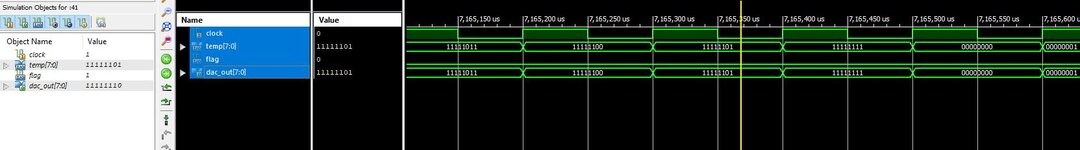
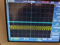
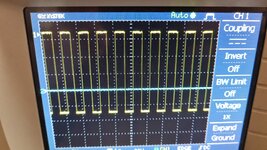
Hello, I am trying to generate different waveforms. I started with generating square wave. Once I managed to do it, I switched to triangular and this is my code below. I am using DAC800 and when I run the simulation it looks to me that the code is good as values of dac_out change as they should but when I implement it on the board I do not get the desired output on the oscilloscope.
Am I making a mistake somewhere in the code?


Code:
library IEEE;
use IEEE.STD_LOGIC_1164.ALL;
--use ieee.numeric_std_unsigned.all;

-- Uncomment the following library declaration if using
-- arithmetic functions with Signed or Unsigned values
use IEEE.NUMERIC_STD.ALL;

-- Uncomment the following library declaration if instantiating
-- any Xilinx primitives in this code.
--library UNISIM;
--use UNISIM.VComponents.all;

entity triangulartest1 is
    Port (clk, reset : in STD_LOGIC;
    dac_out : out STD_LOGIC_VECTOR(7 downto 0));
end triangulartest1;

architecture Behavioral of triangulartest1 is
signal flag : natural;
signal temp : unsigned(7 downto 0) := "00000000";
begin
process(clk)
begin
if temp = "00000000" then flag <=0;
end if;
if temp = "11111111" then flag<=1;
end if;
if (rising_edge(clk)) and (flag = 0) then temp<= temp + "00000101";
dac_out <= std_logic_vector(temp);

elsif (rising_edge(clk)) and (flag = 1) then temp<= temp - "00000101";
dac_out <= std_logic_vector(temp);

end if;
end process;

end Behavioral;
 

You just said the simulation looks correct. Doesn't that mean the code is ok? Have you looked at signals into the DAC? Are they changing? Is there a hardware problem?

BUT, I'm not sure why your simulation worked, though. You're missing temp in your sensitivity list. Also, what's the value of flag when temp does not equal "00000000" or "11111111"? You have an undefined state. Why is temp 8 bits? It looks like it only has two states.

Also, your code is bad form. You should not have two rising_edge statements.

So, yeah, it looks like you need to correct your code.
 

@atancic
There are many things to improve in the VHDL code.
Apart from what barry has to say,
dac_out port is being driven by temp which is defined as a signal, but is not a register. You need to write the VHDL code in such a way that the compiler infers the temp as register. The same with the signal flag.
The reset also needs to be used since it is an input port.

Google how register inference is done in VHDL and also depending on your design use the reset as a sync or async to the clk.
 

You just said the simulation looks correct. Doesn't that mean the code is ok? Have you looked at signals into the DAC? Are they changing? Is there a hardware problem?

BUT, I'm not sure why your simulation worked, though. You're missing temp in your sensitivity list. Also, what's the value of flag when temp does not equal "00000000" or "11111111"? You have an undefined state. Why is temp 8 bits? It looks like it only has two states.

Also, your code is bad form. You should not have two rising_edge statements.

So, yeah, it looks like you need to correct your code.
Thank you. I have just realised that the program does not know what to do between "00000000" and "11111111", along with other mistakes that you mentioned. Thank you. I will try to correct them along with implementing suggestions from @dpaul
--- Updated ---

I updated the code as seen below, started the simulation and did "Force Clock" for clock variable. The temp is incrementing with each rising edge however once it reaches the final value, it resets to zero and I am not understanding why this happens. Shouldn't it start decrementing until it reaches "00000000" again? And believe that the code with the behaviour as described in simulation should give me a sawtooth waveform then implemented on Spartan 6, however the output read from the oscilloscope is a constant "11111111" and flag which is assigned to one of the LEDs on the board is constantly on which means that flag is constantly '1' which does not match with the simulation.
Code:
library IEEE;
use IEEE.STD_LOGIC_1164.ALL;

-- Uncomment the following library declaration if using
-- arithmetic functions with Signed or Unsigned values
use IEEE.NUMERIC_STD.ALL;

-- Uncomment the following library declaration if instantiating
-- any Xilinx primitives in this code.
--library UNISIM;
--use UNISIM.VComponents.all;


entity Triangular is
    Port ( Clock : in  STD_LOGIC;
              temp : inout unsigned (7 downto 0) := "00000000";
              flag : inout std_logic;
              dac_out : out  unsigned (7 downto 0));
end Triangular;
architecture Behavioral of Triangular is
begin

process(clock,flag,temp)
begin
if temp = "00000000" then flag <='0';
elsif temp = "11111110" then flag <='1';
end if;
if (rising_edge(clock)) and (flag = '0') then temp <= temp + "0000001";
dac_out <= temp;
elsif flag ='1' then temp <= temp - "00000001";
dac_out <= temp;
end if;
if temp = "00000000" then flag <='0';
elsif temp = "11111110" then flag <='1';
end if;
end process;
end Behavioral;
 

Attachments

  • triang1.JPG
    triang1.JPG
    67.3 KB · Views: 130
Last edited:

Your code is still wrong
why is temp inout ? You’re going to have multiple drivers.
you STILL have undefined conditions tor temp
why is flag in your sensitivity list?
your “if rising_edge“ statement is a mess. should be something like:

Code:
if rising_edge(clk) then
    if flag=0 then
         Blah...;
    else
          Blah blah...;
    endif;
[code]
 
Last edited:

Your code is still wrong
why is temp inout ? You’re going to have multiple drivers.
you STILL have undefined conditions tor temp
why is flag in your sensitivity list?
your “if rising_edge“ statement is a mess. should be something like:

if rising_edge(clk) then
if flag=0 then
Blah...;
else
Blah blah...;
endif;
Forgive me but I am not into vhdl for a long time, some things that I do are because that is how it was showed to me and most of my knowledge is based on research. The reason why I used temp as inout is to be able to do addition and subtraction.
 

With your help eventually I managed to get a triangular output and I am very grateful. However what I do not understand is why is the amplitude so low. By comparison, the output waveform for square wave is 0-10V however as you can see triangular wave goes from 10 to 9.5V( The two outputs are scaled differently on the oscilloscope) whereas I expected it to go 0-10V. Sorry I might ask too many questions but I like to know the reasoning behind my work, why and how it works, not just to say it works.
 

Attachments

  • triang2.jpeg
    triang2.jpeg
    240.3 KB · Views: 111
  • square1.jpeg
    square1.jpeg
    326.7 KB · Views: 118

Making temp inout has nothing to do with addition and subtraction. You're not using it as an input, it’s an output.

i would verify the DAC output in simulation has the proper range. is your DAC 8 bits?
 

Making temp inout has nothing to do with addition and subtraction. You're not using it as an input, it’s an output.

i would verify the DAC output in simulation has the proper range. is your DAC 8 bits?
Making temp inout has nothing to do with addition and subtraction. You're not using it as an input, it’s an output.

i would verify the DAC output in simulation has the proper range. is your DAC 8 bits?
When I declare it as an output I have an error "Cannot read from 'out' object temp, use 'buffer' or 'inout' ", that is why I set it as inout.
Yes my DAC is 8 bit and in the simulation bits go to "00000000".
 

Attachments

  • sim1.JPG
    sim1.JPG
    45.4 KB · Views: 113

You either have to compile using VHDL-2008 to be able to read outputs, or else use an intermediate signal which gets assigned to the output. e.g.:

Code:
port(
      temp: out unsigned...

signal temp_sig : unsigned...

temp <= temp_sig;
[]

what format does your dac use? Straight binary? Two’s complement?
 
Last edited:

You either have to compile using VHDL-2008 to be able to read outputs, or else use an intermediate signal which gets assigned to the output. e.g.:

Code:
port(
      temp: out unsigned...

signal temp_sig : unsigned...

temp <= temp_sig;
[code]

what format does your dac use? Straight binary? Two’s complement?
I will use intermediate signal then. I am using DAC800, straight binary.
 

I will use intermediate signal then. I am using DAC800, straight binary.
If it’s straight binary, and your output doesn't go below 9.5v, then your high-order bits are stuck high. There’s no other answer. maybe you’ve got a pin-mapping error. Have you looked at the data bits into the DAC with a scope?
 

I don't understand why you moved the temp from being a signal to temp as a inout port (same with flag, which just appears to be a flag to let you know if you are incrementing or decrementing). Both temp and flag were both fine as signals, not sure why you change them to ports, considering you already had the dac_out port to send your temp data to the DAC.
 

I don't understand why you moved the temp from being a signal to temp as a inout port (same with flag, which just appears to be a flag to let you know if you are incrementing or decrementing). Both temp and flag were both fine as signals, not sure why you change them to ports, considering you already had the dac_out port to send your temp data to the DAC.
Ugh, didn’t even notice that.

@atancic, maybe it’s time to start over and do this right.
 

Hi,

Declare the dac_out port as buffer, instead of inout. Declare temp and flag as signals. Flag should be declared as std_logic.

In the process, embed if statement inside case statement. The case statement should be for flag. The if statement should increment temp according to flag and set and reset flag, accordingly, at temp of 128 (I.e. "10000000") and 255 (I.e "11111111").

For the DAC0800, did you notice that B1 is the MSB and B8 the LSB? Could you post your pin assignment and DAC schematic?
 
Last edited:

Theres no reason to declare dac_out as buffer, it’s an out.

Also no reason to use case statement, a nested if-then-else will suffice.
 

If it’s straight binary, and your output doesn't go below 9.5v, then your high-order bits are stuck high. There’s no other answer. maybe you’ve got a pin-mapping error. Have you looked at the data bits into the DAC with a scope?
dac_out is assigned to P6 pins 1-8. The same is used for both square and triangular wave output, however for the square wave generation the output alternates between 0 and 10 as it should.
--- Updated ---

I don't understand why you moved the temp from being a signal to temp as a inout port (same with flag, which just appears to be a flag to let you know if you are incrementing or decrementing). Both temp and flag were both fine as signals, not sure why you change them to ports, considering you already had the dac_out port to send your temp data to the DAC.
When I had changed them to ports, I started to get the desired output from the board. When they are set as signal, the simulation behaves normally however when I flash it to the board and read the output on the oscilloscope it shows a straight line.
 
Last edited:

dac_out is assigned to P6 pins 1-8. The same is used for both square and triangular wave output, however for the square wave generation the output alternates between 0 and 10 as it should.
--- Updated ---


When I had changed them to ports, I started to get the desired output from the board. When they are set as signal, the simulation behaves normally however when I flash it to the board and read the output on the oscilloscope it shows a straight line.
You could still have the pins mapped incorrectly and see this behavior. For “00000000” or “11111111” it doesn’t matter what the mapping is.
 

You could still have the pins mapped incorrectly and see this behavior. For “00000000” or “11111111” it doesn’t matter what the mapping is.
Sorry can you please tell me if I understood "pin mapping" term correctly? I googled about the meaning but so far I did not find any explanation. I thought that bit mapping is dedicating outputs from the code to the on-board pins, LEDs, 7 segment etc. Am I correct or I completely misunderstood? Picture for a reference of how I declared the pins on the board in MIMASV2.ufc .
 

Attachments

  • image_2022-06-04_165000897.png
    image_2022-06-04_165000897.png
    17.9 KB · Views: 107
  • image_2022-06-04_165101714.png
    image_2022-06-04_165101714.png
    30.2 KB · Views: 105

That’s right, you have to make sure that the LSB of dac_out gets mapped to the FPGA pin that’s connected to the DAC LSB pin, etc. The constraint file is half the story, the schematic (or PCB layout) is the other half.
 

Status
Not open for further replies.

Part and Inventory Search

Welcome to EDABoard.com

Sponsor

Back
Top