Continue to Site

Welcome to EDAboard.com

Welcome to our site! EDAboard.com is an international Electronics Discussion Forum focused on EDA software, circuits, schematics, books, theory, papers, asic, pld, 8051, DSP, Network, RF, Analog Design, PCB, Service Manuals... and a whole lot more! To participate you need to register. Registration is free. Click here to register now.

Transistor for microwave amplifier

Status
Not open for further replies.

tomato_sos

Junior Member level 3
Joined
Jan 20, 2011
Messages
26
Helped
1
Reputation
2
Reaction score
1
Trophy points
1,283
Activity points
1,495
Hi all,
I am new in designing microwave amplifier. Just get started only.
I am currently doing a microwave amplifier designing project.

I am using ATF-55143 from AVAGO.
My design is at 2.5 GHz. After calculate the stability, the \Delta <1, K<1, even the \mu <1.

How to determine whether it is stable or not ?


Anyone have other suggestion on the transistor?
I was thinking AT-32032, but it is discontinued.
 

Thanks for the inputs. I wanna know, why there is unstable ,since the product claim it can support up to 6 Ghz?
 
  • Like
Reactions: S.Ali

    S.Ali

    Points: 2
    Helpful Answer Positive Rating
You can make any transistor in the world to be unstable, whatever datasheets claims.
Check your PCB layout, the input/output impedances, the parasitic source inductance, any kind of positive feedback, etc.
 
well u have to make it stable first then u can do matching to get maximum output from it....
u can refer Gonzalez for the basic methods on how to stabilize the trasistor using smith chars OR u cn diretly use any RF software for that.....
 
Well, unfortunately you have to match for output AND stability in the same time.
Actually I would match for stability first and for other things next (gain, output, NF).
You can sell an LNA with little bit less gain or NF, but definitely an unstable LNA it will stay in your drawer.
 
Check the stability circles first to see which impedances make your transistor unstable.If these impedances are extreme ones, you can use this transistor even it's unstable..
 
I have another problem.

Hi all, I get a "without matching" S parameter from AVAGO ATF-55143.
How I going to match it 1st, before I can calculate the K factor for the stability?

I have read some threads. I think the way will be: use ADS to simulate it, and add inductor in the input. I heard we can use MMIC amplifiers inside the ADS to do the simulation. Right ?
I have no idea how to match it...

Anyone can actually guide me? Step by step.

For your information, the only way I learn is:
1. Get S parameter, calculate the K etc etc. Determine stability.
2. Draw the Conjugately Matched smith chart for the Dstub and Dline for input/output matching network.
( I learn these from Microwave Engineering by Pozar.)
The example inside the book is "after matching" S parameter, so I can design the matching without any problems. Since the S parameter is "without matching" , then how I going to process the works?

---------- Post added at 22:40 ---------- Previous post was at 22:31 ----------

updated: I download the QuickSmith. I dont know how to use. I able to check K and \Delta value and determine whether it is stable or not.
 

Anyone can help me?
From the S parameter I get from the datasheet, it is "without matching". Ya, I know I need to match it.
But from the beginning, I calculate the K and Delta factor, both are unstable. I know it is a "without matching" S parameter datasheet.
After match then only it will be stable. But I dont know how to match it as I need S parameter to draw the Stub-microstrip matching.
If I use the existing S parameter, the Dstub/Dline that I get from the conjugately match smith chart is all outside the smith chart. Yet again, It show "without matching" situation.

I cannot process matching with this S parameter. How I going to design amplifier? Anyone meet this problem before? It is my school project. I am not asking for full solution, I just asking how to cope with this problem. I am willing to learn. Really appreciate any helps from you all.
 

I am using ADS( what my supervisor told me, but himself dont know how to use it. So no guide from him). I am learning to use now. Just from the examples I found on the net.
I now still in the early stage of design, I just have a S parameter datasheet of ATF-55143 (pdf from AVAGO). I didnt have any *.s2p file.

So at first, I need to measure transistor?
 

You need to read the 2 attached pdf file so you will know what you suppose to do. One is a tutorial by a user of this forum named "boy". It's very good tutorial for beginner so I save it for days like this.
The other one is an app note by Avago using the same device at 2.3GHz. Yours is 2.5GHz and it's close enough.
I also attached a ATF-55143 model I got from Avago site, just in case you can't get it. You need to change the file suffix from .zip to .zap because this forum doesn't let me up load a .zap file. Use ADS to unarchive the zap file to a project. With these 3 files, you should be able to handle your project.
 

Attachments

  • atf55143_010407.zip
    18.3 KB · Views: 126
  • lab_1_linear_lna_design.pdf
    2.3 MB · Views: 280
  • AV01-0376EN+AN_5294+15Jul10.pdf
    159.8 KB · Views: 196
Thank you, UKnowWhat.
I still downloading the attachments. My country internet download is so slow now. around 2kbps only.

---------- Post added at 15:01 ---------- Previous post was at 14:18 ----------

i will download on tomorrow, cos the internet is keep on disconnecting.
 

I have download the tutorial by BOY. Very details and clear. I will study it now. Thanks for the help anyway!!!
 

any one having the book
Tri T. Ha, "Solid-State Microwave Amplifier Design," John Wiley & Son, 1981
please send a post to me if any one having this book.
its good book for designing amplifiers


I read the book : microwave transistor amplifiers 2nd Ed by gonzalez. It is a good book. Now I can understand more abit on the transistor amplifier design.
From the book, I know I can use resistor to stable the transistor at desired frequency. From the book, page 226, Example 3.3.2, it show me how to do it.
But then I have a problem to ask:

My ATF-55143 S parameter at 2.5GHz is:

mag ang
S11 0.657 -123.7
S21 6.159 86.6
S12 0.084 23.7
S22 0.503 -66.3

From my lecturer, it is a Unilateral.
But from the Gonzalez, it should be Bilateral ( From page 243 ), since the S12 is 0.084 ( for my case)
1. Is it bilateral case? ( I was so wrong from the beginning, cos listen to my lecturer Unilateral case)
2. How if the input and output circles are both outside range of the Smith Chart?
I have draw the input output circles, both are outside the smith chart. I cannot apply the technique shown in Page 226.
My project didnt fix any gain or desired results.
Just design an amplifier that amplify signal. That is all.
Now I found out that, I am so lost. Whatever I learn from school, not so helpful as lecturer is teaching the wrong concept.
 

Now, I just assume it is an unilateral case.
Gamma s = S11* = 0.657<123.7
Gamma L = S22* = 0.503<66.3

After I drew the input output smith chart, I get:
Input
D line = 0.145 \lambda
D stub = 0.168 \lambda

Output
D line = 0.313 \lambda
D stub = 0.138 \lambda

My \lambda guide at 2.5Ghz is 0.057208m

Now I get my measurements for all the microstrip matching.
How do I simulate it with ADS?
I know I just draw the microstrip line, but how about the transistor?
Is it I unachieve the .zap file, then add in the microstrip line ?

---------- Post added at 14:21 ---------- Previous post was at 14:19 ----------

I am using microstrip stub matching. not using Lumped components.
 

Here I attach some ADS circuit files, I was stucked at there.

I have done some calculation and smith chart plotting. I hope I get it right. Please correct me if I have done something wrong :sad:

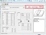
I also attached my print screen of line_cal from ADS. I not sure this is for what purpose, cos I was following the internet tutorial. Is it the transmission line for both input and output connector?

From the file Transistor.pdf, I get the D line and D stub measurement for both input and output, but then how about the width ? How do I determine / calculate the width of the microstrip line ?
 

Attachments

  • Transistor.pdf
    3.2 MB · Views: 157
  • line_cal.JPG
    line_cal.JPG
    125.8 KB · Views: 122
  • ADS circuit.rar
    14.6 KB · Views: 117

Status
Not open for further replies.

Part and Inventory Search

Welcome to EDABoard.com

Sponsor

Back
Top