Continue to Site

Welcome to EDAboard.com

Welcome to our site! EDAboard.com is an international Electronics Discussion Forum focused on EDA software, circuits, schematics, books, theory, papers, asic, pld, 8051, DSP, Network, RF, Analog Design, PCB, Service Manuals... and a whole lot more! To participate you need to register. Registration is free. Click here to register now.

Transformer Symbol Help Needed

Status
Not open for further replies.

EE Follower

Newbie level 4
Joined
Sep 12, 2012
Messages
5
Helped
0
Reputation
0
Reaction score
0
Trophy points
1,281
Activity points
1,313
Hi,
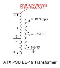
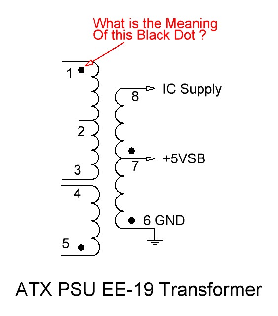
I have added the picture of ATX PSU EE-19 Chopper Transformer for +5VSB Section . In the picture Black Dot stands for What ?? Is it related with transformer windings or other things ?? What is the meaning of these Black Dots ?? If anyone explain it, it will be very helpful for me .


Thanks
 

The purpose of the dots is to indicate the direction of each winding relative to the other windings in the transformer. Voltages on the dot end of each winding are in phase, while current flowing into the dot end of a primary coil will result in current flowing out of the dot end of a secondary coil.

**broken link removed**
 

That black point accord to coils polarity (according to direction of turning wire around the ferrite )
 

Hi,
It represents the the polarity assume at an instant the dot marked pin is +ve compared to the other pin in the same winding then all other dot marked pins will be +ve in their respective windings.
regards ani
 

Thank you Guys .

One more thing - Can I measure the voltage between these two Pin (Dot and Without Dot Pins) ? I mean - Meter's Black Probe to "Without Dot" Pin and Red Probe to "Dot pin" . Can I measure the voltage in this way ?? If not, then how can I measure voltage of these two pins ??
 

Thank you Guys .

One more thing - Can I measure the voltage between these two Pin (Dot and Without Dot Pins) ? I mean - Meter's Black Probe to "Without Dot" Pin and Red Probe to "Dot pin" . Can I measure the voltage in this way ?? If not, then how can I measure voltage of these two pins ??
Hi,
Yes, put the meter in AC range with approximate voltage setting and then mesure the voltage
 

You can put probe any side of the pin it is not issue, but multimer shouldbe put AC Mode...
 

You can measure mentioned by oscilloscope.
However I think you cannot measure voltage by multimeter because of transformer frequency at (ATX SMPS) is approximately 40-120khz and this need to special multimeter or oscilloscope to detect it.
 

Again Thank you Guys .

But Can I ask - Why is it AC ?? Transformer's Pin1 is connected directly with Capacitor +Ve which is 320V and Pin3 is connected directly with Transistor 2SC5027 Collector and Pin5 is directly connected with Capacitor -Ve . Is Transistor 2SC5027 creating AC here ?
 

Yes, Dc source connected to 320v DC by a switch that make a 40-110khz ac for H.F transformer
 

Status
Not open for further replies.

Part and Inventory Search

Welcome to EDABoard.com

Sponsor

Back
Top