Continue to Site

Welcome to EDAboard.com

Welcome to our site! EDAboard.com is an international Electronics Discussion Forum focused on EDA software, circuits, schematics, books, theory, papers, asic, pld, 8051, DSP, Network, RF, Analog Design, PCB, Service Manuals... and a whole lot more! To participate you need to register. Registration is free. Click here to register now.

Transformer isolated IGBT switch -- Zener diode heating

Status
Not open for further replies.

trubetz

Newbie
Joined
Aug 8, 2022
Messages
2
Helped
0
Reputation
0
Reaction score
0
Trophy points
1
Activity points
23
Good day everybody

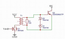
I am trying to make a transformer isolated switch for an IGBT; a part of the circuit is shown below.
switch.jpg
It includes a low-current side switched by IRF644 MOSFET (I just have these on hand) and a home-wound transformer, all driven by SG3525.
The secondary winding is loaded onto a 100 ohm resistor in parallel with two Zener diodes for TVS. My problem is that when turned on, the D1 heats immensely during the turn-on part of the cycle. From what I can see on the power supply, it sinks a lot of current (VCC = 12V, and the total power consumption is in the 800 mA range, and it looks like at least 0.5A goes through the Zener). My question is, what is the proper way of suppressing transients? I saw a lot of solutions using transistors, but I would like some descriptions where I can understand what I am doing rather than just copying the layout. Your help is much appreciated.
 

The circuit is missing a series capacitor.
Also, when Q1 turns off, the pri magnetising current will overvoltage the Q1.
Try this document to find your way...

Laszlo Balogh.
High speed mosfet driver design...

Figure 35 . page 32 looks good for you.
Or fig 39, page 35.....has no series capacitors, but the pri is driven with equal and opposite volt.seconds in each direction, so it gets reset.
But mind the sec high pulse height will depend on the duty cycle.

Attached is a nice GDT for you. In LTspice

The following SMPS course, under the headings "Gate Drive" and "Gate Drive Transformer" has some offerings in LTspice etc for you to peruse.

SMPS course_little folders
https://drive.google.com/file/d/1WvElhDNfHI0EBei4rouSNEdWWTO1oCtJ/view?usp=sharing

I am glad you asked, as it is good to do so , and it will be massively financially beneficial to the owner of your company that you have taken to the forum. Have no fear that you give away company secrets, as this is the "electrician level" of electronics, and too general to be company IP.....its more like Electrician's knowledge.
 

Attachments

  • LLC with chosen gate drive transformer _2xGDT.zip
    4 KB · Views: 110
Last edited:
Incomplete requirements, what's maximal on- and minimal off- time? What's transformer main inductance and saturation Vs? Presumed transformer has 1:1 winding ratio, why are you using 10V zener?
 
Okay, these are really good questions; I operate at a fixed duty cycle around 45% as of now, making the on time about 23 us, and the off time 27. The transformer inductance is 43 uH. No idea about the saturation (no idea how to measure it), but judging by the overshoots I get with no zeners, I am not reaching that. As for the zeners, now that I think about it, there is absolutely no reason I should not use 12 or even 15 volt indeed.
 

The zeners on the gate could be as high as 18V without issue - the 10V zener is the reason for the high current ( this should be pretty obvious - assuming the Tx is 1:1 )

The 100 ohm res will pull 54mA ave @ 45% D, plus the energy from the demagnetising Tx

so at least a 1W type needed to limit the Trise

A 33V zener across the mosfet is a good idea, giving 33-12 = 21V of reset on the Tx - some of this energy will go into the sec side zeners and the 100E res.

Your GD Tx must be good for 1500V at least to be safe, is there a spec of the V.uS on the Tx ?

you should be inside that to limit the peak flux and avoid saturation.

good luck ...!
 

Also, Infineon now do "coreless" technology, which is literally an isolated IGBT driver on a chip if you want...


You do need another isolated supply for the hi side, but you can buy that as a module aswell if you want.
--- Updated ---

Also, did you interleave wind to get low leakage inductance?
Or you could do bifilar winding of pri and sec with say Triple insulated wire to try and keep the interwinding capacitance down.

The 18V zener mod by Easy Peasy is of course needed, so to the 33V zener.......though your circuit is the same as they were using for testing, at a big RF/Power company i once worked at....i proposed adding something to reset the primary, and it was just fobbed off, and they said "no need to fix if not broken", so i guess your cct has its own way of resetting using the parasitics etc.

IRF644
 
Last edited:

Status
Not open for further replies.

Similar threads

Part and Inventory Search

Welcome to EDABoard.com

Sponsor

Back
Top