Continue to Site
Follow along with the video below to see how to install our site as a web app on your home screen.
Note: This feature may not be available in some browsers.
Hi Ratch, i have see your attachment, actually i rather confuse with how you solve that equation..in your result i see an j is alone,but i consider in equation j must follow with jωC2..
I solve your equation using my way...you can see in my attachment..
I solve the transfer function of the circuit in 2 ways,and all of that give me the same transfer function..i directly assume that OP is ideal..because if it is non ideal the analysis become very confusing..
Hi FvM,,the complete analysis see in my attachment...i have written numerator and denominator in zero pole form..
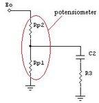
if you have see my attachment, if the potensiometer don't burden the circuit, the transfer function will be same with transfer function which FvM did..
what do you think? .
")
Hi Ratch, i have see your attachment, actually i rather confuse with how you solve that equation..in your result i see an j is alone,but i consider in equation j must follow with jωC2..
Me neither. But others contributing to this forum are required to use an understandable form, because they are teaching the stuff, writing reports for coworkers or customers, or passing examinations.I will never sit for an examination again.
I think, writing numerator and denominator as products of zeros and poles. It gives an intuitive view on the transfer function's properties. Or other forms found in text books. Surely no detached "j".What is the "standard form"?
FvM; Eo/Ei = -1/k * (1 + jωR3C2)/jωR4C2[/QUOTE said:at 1st sight, i can see that the circuit have pole at ω = 0 and zero at -1/R3C2,
so i know that magnitude response will decrease -20dB each decade (start at ω = 0) until ω = 1/R3C2 after that the magnitude response will be constant.
and if the tf represent like you did,
Quote from your attachment,
Eo/Ei = (-R3ωC2 + j)/ωC2R4.
i can't make analysis like that at first sight.
How do you think?
i'm an undergraduate student.i'm learning about this and i'm not yet understanding it well.so,correct me if i'm wrong,
How do you think?
i'm an undergraduate student.i'm learning about this and i'm not yet understanding it well.so,correct me if i'm wrong,