Welcome to our site! EDAboard.com is an international Electronics Discussion Forum focused on EDA software, circuits, schematics, books, theory, papers, asic, pld, 8051, DSP, Network, RF, Analog Design, PCB, Service Manuals... and a whole lot more! To participate you need to register. Registration is free. Click here to register now.
Transfer function from what input to what output ?
Coupled to another one, or to its own coils ?
What are the units of interest ?
Closed path or open path ?
For what application ?
What geometry ?
Material ?
In short words, if you are referring to a generic stick magnet, there is not a simple calculation or a simple formula, but it is necessary perform a numeric simulation.
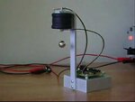
Iam building this electromagnet for levitating a magnet below it using hall sensor as position sensor. Find the image for clearity.
However I have to find the transfer function of the whole system to apply PID on it, as the system is unstable inherently.
Electromagnet is wound around a long SCREW of 22 Gauge wire. N=1000, L=7cm, and D=4cm.
Due to this force depends on several factors, this would become impractical to get it by calculations based on the physics, therefore you could first measure the force required to sustain the ball at several points of the Y axis. I cannot seen how to do that dynamically, so you could make an apparatus to fasten the ball steadily. I could suggest you do something like that:
It is just an illustrative picture, cleaned useless information.
Course, being metalic, the coil should be kept appart from the ball.
Note that the stretch of the coil is proportional to the force. Once you have the force plotted, could make a regression to determine for instance a polinomial approximation so that this would represent the plant to be reached by the the PID control.
Anyway, I see an additional complexity at this control due to even being the ball at a determined position, you are dealing with different forces ( models ) depending on what direction you need drive the ball. If you release the energy the ball will fall much faster than would rise if applied the same force to return to the original position.
Besides measuring the position dependent force empirically, it can be also determined in a magnetostatical finite element analysis. Due to the axisymmetric geometry, a 2.5-D tool like Quickfield can be used.
The non-linear force function is the most difficult part, but there's also the second order differential equation describing the relation of force and position.
I also don't understand how you want to utilize a hall sensor as position detector, but that's a different story.
Nice work yes. But it shows also that the system has a double nonlinearity which can't be compensated by a basic PID.
- position dependency of magnetic force. It's assumed as a simple 1/x function in the paper, probably not exactly correct for the given magnet geometry
- square law F versus I of an electromagnet
This site uses cookies to help personalise content, tailor your experience and to keep you logged in if you register.
By continuing to use this site, you are consenting to our use of cookies.