Continue to Site

Welcome to EDAboard.com

Welcome to our site! EDAboard.com is an international Electronics Discussion Forum focused on EDA software, circuits, schematics, books, theory, papers, asic, pld, 8051, DSP, Network, RF, Analog Design, PCB, Service Manuals... and a whole lot more! To participate you need to register. Registration is free. Click here to register now.

Traffic Light Simulator (555) - Trouble Shooting Help

Status
Not open for further replies.

Gr3x

Junior Member level 1
Joined
May 24, 2012
Messages
17
Helped
0
Reputation
0
Reaction score
0
Trophy points
1,281
Location
Ontario
Activity points
1,401
So I hooked up the circuit based off of this schematic.

When I apply power the red LED comes on right way and stays on. I'm having a hard time finding the issue, anybody see the problem?

My circuit:

Traffic LED2.jpgtraffic LED.jpg

More pics available upon request
 

Check connection for 100k resistor on the left side circuit (must be connected to pin 3).
 

Attachments

  • traffic s.png
    traffic s.png
    648.3 KB · Views: 161
Also need to change connection for the 220 ohms resistor on the right side circuit. (change from pin 2 to pin 3)
I assume that each 'red line power rail' connected to + power supply and the 'blue line power rail' connected to the GND… :-D
 

Attachments

  • traffic s2.png
    traffic s2.png
    467.7 KB · Views: 109
Last edited:
Good eye,

I fixed up the circuit a bit but I'm still having the same problem (Red LED comes on and stays on, no other LED's turn on)

Pic:

CMAN.jpg
 

Move the orange LED pin and the resistor pin to an empty slot. :-D
 

Attachments

  • Trafficv3.png
    Trafficv3.png
    691.3 KB · Views: 108

... Just realized that I uploaded the wrong pic haha woops

Here:

CMAN.jpg

NOTE: I moved the orange LED and resistor to new rung, no result
 

Please take some pictures from different angles. :-D

---------- Post added at 14:50 ---------- Previous post was at 14:47 ----------

Please check the power supply voltage:
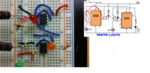
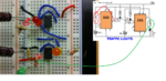
A supply voltage of 9v to 12v is needed because the second 555 receives a supply of about 2v less than rail.
 

Im using a 9V power supply... 6 1.5V batteries in series.
 

I don’t have a clear picture to check the leads position for the green LED. Need more photos...
 

Different views of green & red LED connections. Let me know if you want more.

redled.jpg

greenled.jpg
 

First try to test the left side 555 circuit by connecting pin 8 to the 9V power supply.
 

Attachments

  • 555 v1circuit.png
    555 v1circuit.png
    619.6 KB · Views: 114

Ok did this ... Green LED flashes fast and red LED stays on. The green LED has been turning on this whole time alsoa long with the red. I didnt notice at first because its extremely dimmed. Maybe I need the 12 volts?
 
Last edited:

Check the 100k resistor connection between pin 2 and pin 3 (red LED circuit side). Check 100uF capacitor connection between pin 2 and GND. Disconnect and reconnect again the 555 circuit on the breadboard.
 

Isnt working man ... Might throw in the towel here lol
 

All we need is just a little patience. :-D
Left and right circuits looks very similar.
If you keep the pin 8 disconnected from pin 3 and you re-connected to the power supply the RED and GREEN LEDs must blink (almost double frequency for the GREEN LED).
Try to compare conections for the two circuits, and swap the two 555s.
 
Status
Not open for further replies.

Similar threads

Part and Inventory Search

Welcome to EDABoard.com

Sponsor

Back
Top