manishanand14
Full Member level 4
- Joined
- Sep 3, 2011
- Messages
- 203
- Helped
- 10
- Reputation
- 20
- Reaction score
- 9
- Trophy points
- 1,308
- Location
- Bangalore ,India
- Activity points
- 2,572
Dear Friends
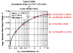
Please tell me the max output current which TL081,TL082,TL084 can deliver.
If we use all 4 op-amps of TL084, then is there any chance of loading.
Please tell me the max output current which TL081,TL082,TL084 can deliver.
If we use all 4 op-amps of TL084, then is there any chance of loading.