Vermes
Advanced Member level 4
It is a thermoscaner of own construction, which can be made at home by electronics who are interested in thermography.


The device uses IR sensors and a copy of FMA sensor. Such sensors are described HERE.
Due to the use of gyroscopes and accelerometers in IMU (immersion unit), this kind of optical solutions are not currently used for the position reading. As you know, the sensor detects a temperature and that function is used to create a thermal image of the environment. Typically this kind of sensors is not designed for that use, but you can make some experiments in this field.
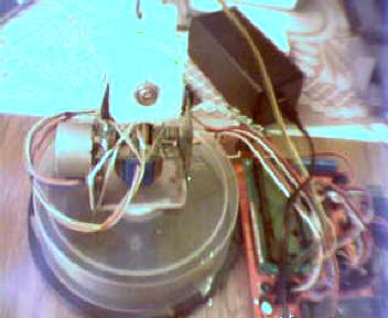
The construction of this device is very simple. Microcontroller controls two stepper motors in X and Y axis. There is also ADC input for analog reading of the output. Then data are send to the PC and displayed in the screen in form of an image.
After assembly of prototype of mechanical scanner of X and Y axis. A prototype board with microcontroller for controlling the stepper motor drivers was added. The stepper motors with gears operating in 1-2 mode, ensured 1024 steps for 90 degrees of rotation angle, what is a high accuracy as for such an application. It is easy to write program for the microcontroller. Data is sent from the microcontroller to the PC through a USB cable.
You also have to write a program for the PC to receive data and form an image from it.
As the FOV (field of view) of the sensor is 90 or 120 degrees, it has to be reduced to about 5-10 degrees.
When you do not have lenses for IR band, the “reducing” optics can be made at home. It reduces 90 degrees to about 10 degrees. To compensate the significant drop of the sensor sensitivity, you will need a processing of the amplifier, which was attached in standard to the Z sensor of the remote control location. The prototype uses a board of the sensor with removed one sensor (normally there are two such sensors) and modified signal amplifier.
To ensure the isothermal conditions inside the measure circuit, to reduce the impact of temperature of the executive circuit and ensure the constant reading of the background radiation, the most recommended material for this purpose is Styrofoam.

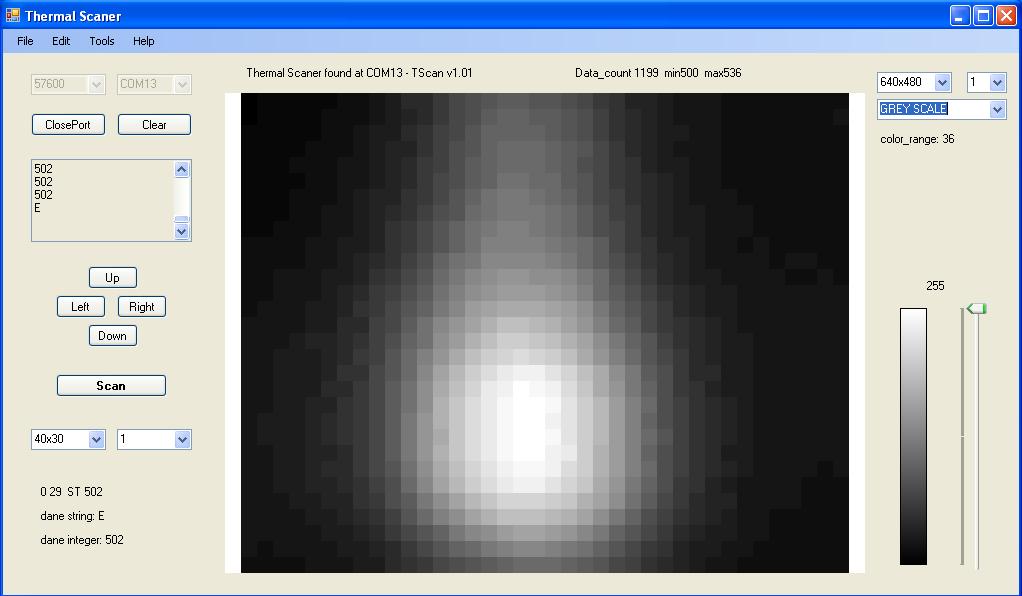
Then it is time for tests. Try to find a warm object (such as human body) and scan it:
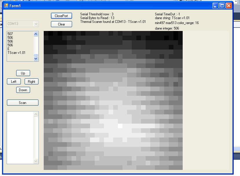
The sensor has its own inertia and it has to be compensated by the withdrawal of each pixels of the image lines in relation to each other, and thus you have to add the appropriate control in the program, to improve the image immediately. The scan resolution is 40x30 is sufficient for experiments. Such scanning takes about 1:40 minute (almost 2 minutes).

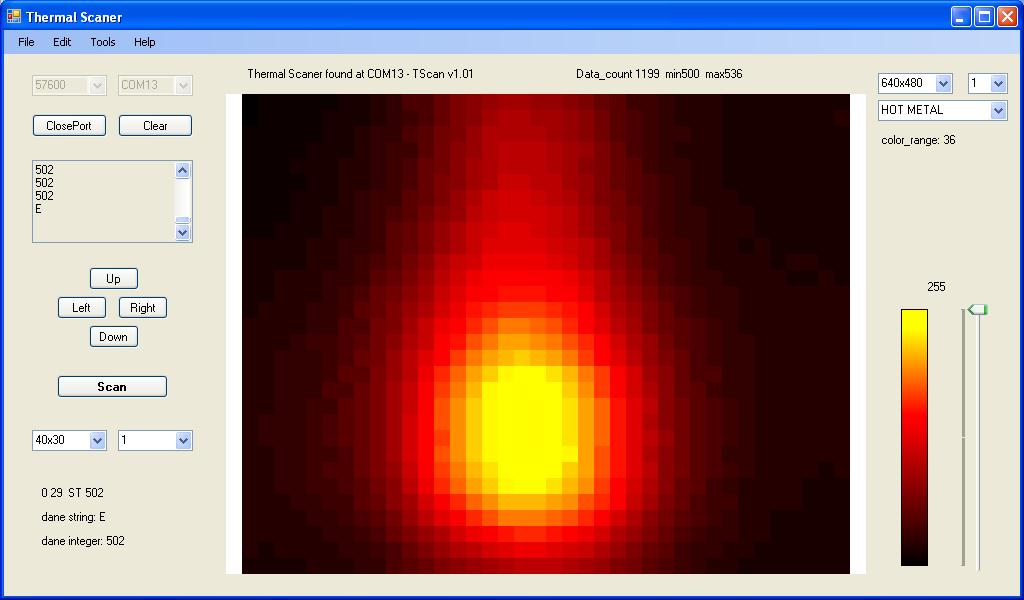
The next stage of construction – adding color:
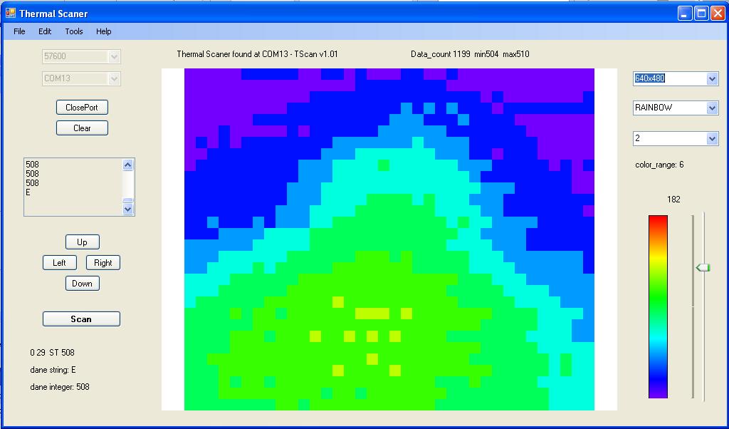
And image of furnace:


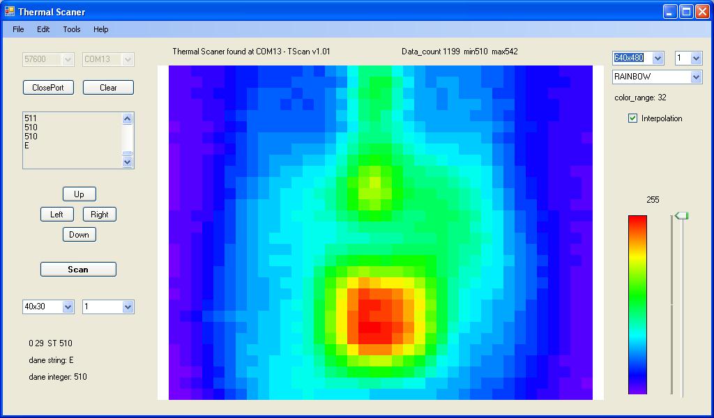
As you can see, the angle of view was still too wide. It had to be narrowed down. Thus the optics was to be improved as well as interpolation was to be add:


Video of the operation:
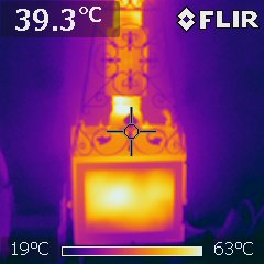
And at the end, the same furnace seen in the factory thermovisual camera:

Link to original thread - Termografia DIY? A dlaczego nie - termoscaner - eksperymenty