Continue to Site

Welcome to EDAboard.com

Welcome to our site! EDAboard.com is an international Electronics Discussion Forum focused on EDA software, circuits, schematics, books, theory, papers, asic, pld, 8051, DSP, Network, RF, Analog Design, PCB, Service Manuals... and a whole lot more! To participate you need to register. Registration is free. Click here to register now.

The I2C accelerometre freezes

Status
Not open for further replies.

Mondalot

Junior Member level 3
Joined
Sep 28, 2013
Messages
29
Helped
0
Reputation
0
Reaction score
0
Trophy points
1
Activity points
235
Hi,

I have mounted on a protoboard with PIC18F26K22 and accelerometer MMA7455, when I take a while to see values on the screen freezes (hang down), I have to do a reset.

The pic works to 5V and MMA7455 works 3.3V , Among them is connected TXS0108EPWR (8-Bit Bi-directional, Level-Shifting, Voltage Translator for Open-Drain and Push-Pull Applications)

anyway, when the Pic and MMA7455 operate to 3.3 volts,
with their respective resistors (2.2K) on the SDA and SCL lines to 3.3V also froze the I2C bus

What causes might be?

THX.
 
Last edited:

This why I'm no longer using h/w I2C master. Hard to manage the bus errors. In your case may be ACK signel was lost and your pic is waiting forewer. You should be carefull when waiting some events without timeout.
 

Hi,

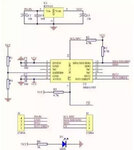
Please give: schematic, code and error description like status of the interface lines during error condition.
How often do you read the sensor contents? (N times per second...)
Scope pictures could also help.

Klaus
 

Hi

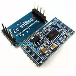
The circuit board with MMA7455 buy it on ebay.
The values are corrects 0 to 255 until it freezes.


PCB MMA7455.JPG
Scheme MMA7455.jpg


Code Bas:
Code:
    Device = 18F26K22
    Declare Xtal 16   

Config_Start
 FOSC = INTIO67 'INTIO7	'INTIO67 	'HSHP  ' HS oscillator (high power > 16 MHz)
 PLLCFG = On       ' Oscillator multiplied by 4
 PRICLKEN = On     ' Primary clock enabled
 FCMEN = OFF           ' Fail-Safe Clock Monitor disabled
 IESO = OFF            ' Internal/External Oscillator Switchover mode disabled
 PWRTEN = OFF 'On           ' Power up timer enabled
 BOREN = SBORDIS 'OFF       ' Brown-out Reset enabled in hardware only (SBOREN is disabled)
 BORV = 190            ' Brown Out Reset Voltage set to 1.90 V nominal
 WDTEN = Off           ' Watch dog timer is always disabled. SWDTEN has no effect.
 WDTPS = 128           ' Watchdog Timer Postscale 1:128
 CCP2MX = PORTC1       ' CCP2 input/output is multiplexed with RC1
 PBADEN = Off          ' PORTB<5:0> pins are configured as digital I/O on Reset
 CCP3MX = PORTC6       ' P3A/CCP3 input/output is multiplexed with RC6 
 HFOFST = On           ' HFINTOSC output and ready status are not delayed by the oscillator stable status
 T3CMX = PORTC0        ' Timer3 Clock Input (T3CKI) is on RC0
 P2BMX = PORTB5        ' ECCP2 B (P2B) is on RB5                   (EXTMCLR = Enable MCLR/Disable RE Input)
 MCLRE = INTMCLR	   ' MCLR pin enabled, RE3 input pin disabled  (INTMCLR = Disable MCLR/Enabled RE Input)
 STVREN = Off          ' Stack full/underflow will not cause Reset
 LVP = Off             ' Single-Supply ICSP disabled
 XINST = Off           ' Instruction set extension and Indexed Addressing mode disabled (Legacy mode)
 Debug = Off           ' Disabled
 Cp0 = Off             ' Block 0 (000800-001FFFh) not code-protected
 CP1 = Off             ' Block 1 (002000-003FFFh) not code-protected
 CP2 = Off             ' Block 2 (004000-005FFFh) not code-protected
 CP3 = Off             ' Block 3 (006000-007FFFh) not code-protected
 CPB = Off             ' Boot block (000000-0007FFh) not code-protected
 CPD = Off             ' Data EEPROM not code-protected
 WRT0 = Off            ' Block 0 (000800-001FFFh) not write-protected
 WRT1 = Off            ' Block 1 (002000-003FFFh) not write-protected
 WRT2 = Off            ' Block 2 (004000-005FFFh) not write-protected
 WRT3 = Off            ' Block 3 (006000-007FFFh) not write-protected
 WRTC = Off            ' Configuration registers (300000-3000FFh) not write-protected
 WRTB = Off            ' Boot Block (000000-0007FFh) not write-protected
 WRTD = Off            ' Data EEPROM not write-protected
 EBTR0 = Off           ' Block 0 (000800-001FFFh) not protected from table reads executed in other blocks
 EBTR1 = Off           ' Block 1 (002000-003FFFh) not protected from table reads executed in other blocks
 EBTR2 = Off           ' Block 2 (004000-005FFFh) not protected from table reads executed in other blocks
 EBTR3 = Off           ' Block 3 (006000-007FFFh) not protected from table reads executed in other blocks
 EBTRB = Off           ' Boot Block (000000-0007FFh) not protected from table reads executed in other blocks
Config_End

OSCCON =  %11110000
OSCCON2=  %00000100

Declare SCL_Pin = PORTC.3     '  SCL connected to this pin for use with Busin and Busout
Declare SDA_Pin = PORTC.4    '  SDA connected to this pin for use with Busin and Busout
Declare Slow_Bus On		     ' Slows the bus speed when an oscillator higher than 4MHz   

ANSELC = %00000000             ' Set portC Digital
TRISC   = %00000001             ' Set PortC I/O


   MMA7455_W_OFFSET(0,4,8) ' (X,Y,Z) 'Call Lib and Write Offset 

Ini:

   MMA7455_ReadDate()      'Call Lib read Data x,y,z

    Print At 3,50,"X: ",Dec ACE_X
    Print At 4,50,"Y: ",Dec ACE_Y
    Print At 5,50,"Z: ",Dec ACE_Z
  
   DelayMS 100

Goto Ini
END


Code Lib:
Code:
$ifndef __MMA7455_INC_
$define __MMA7455_INC_
'
  
' MMA7455 variables
'
	Dim ACE_X As Byte   ' Read Value X
	Dim ACE_Y As Byte   ' Read Value Y
	Dim ACE_Z As Byte   ' Read Value Z
        Dim OFF_X As Byte  ' Value Offset X
	Dim OFF_Y As Byte  ' Value Offset Y
	Dim OFF_Z As Byte  ' Value Offset Z
'

' MMA7455 register addresses
'
     $define C_REG_MM7  $16   ' 16 DIRECCION CONTROL REGISTRO
     $define RE_ACELERO $3A    ' 0011 1011 3A ALIAS DEL CODIGO PARA LEER 
     $define WR_ACELERO $3B   ' 0011 1010 3B ALIAS DEL CODIGO PARA ESCRIBIR 
     $define LEO_X_REG  $06    ' Read register X (8-Bit)
     $define LEO_Y_REG  $07    ' Read register Y (8-Bit)
     $define LEO_Z_REG  $08   ' Read register Z (8-Bit)
     

$ifndef False
    $define False 0
$endif
$ifndef True
    $define True 1
$endif

'----------------------------------------------------------------------------
    GoTo _MMA7455_Main                   ' Jump over the routines
'----------------------------------------------------------------------------
    
$define MMA7455_W_OFFSET(hXX, hYY, hZZ) '
    OFF_X = hXX                                 '
    OFF_Y = hYY                                 '
    OFF_Z  = hZZ                                '
    GoSub _MMA7455_W_OFFSET

_MMA7455_W_OFFSET:
    
    HBStart	 	 	 		    	               ' Open I2C 
     HBusOut WR_ACELERO ,C_REG_MM7,[$65]    ' Write MCTL Register $16, sending               
     HBusOut WR_ACELERO ,REG_XOFFL,[OFF_X] ' X LowByte Pag 14 DataSheet 
     HBusOut WR_ACELERO ,REG_YOFFL,[OFF_Y]  ' Y LowByte
     HBusOut WR_ACELERO ,REG_ZOFFL,[OFF_Z] ' Z LowByte
   HBStop	                          
Return

        
$define MMA7455_ReadDate() GoSub _MMA7455_ReadDate

_MMA7455_ReadDate:

   ' MMA7455_SendDate
   
    HBStart
     HBusIn RE_ACELERO ,LEO_X_REG,[ACE_X] 
     HBusIn RE_ACELERO ,LEO_Y_REG,[ACE_Y]
     HBusIn RE_ACELERO ,LEO_Z_REG,[ACE_Z]
    HBStop
    DelayMS 100			
      
Return

'----------------------------------------------------------------------------
_MMA7455_Main:

$endif  ' _MMA7455_INC_
 
Last edited:

I do not understand, explain better.

THX.
 

Hello!

I do not understand, explain better.
THX.

I guess he wants to say he doesn't understand your code. Me neither. What language is this?
A kind of basic?

Anyway, if your code just consists in reading an accelerometer, it should be pretty simple. One good way
to verify: put a scope on SDA and SCL. If you can find a scope that interprets I2C (displays numbers at the
screen), it's even more convenient. That said, if you want to maximize your chances to get useful replies,
you should write code in C, as everybody usually does. And once you know how to do it in C, then it will
not be very difficult to translate it into your favorite language.

Beside this, I don't agree with the idea of not using a hardware I2C engine if it's on the processor. It's
really a good way to get 95% of the job done. I just wrote an I2C driver (or at least part of it, just to access
the acceleration and gyro of a MPU9150). It's really simple to do it with the hardware, otherwise you will
really spend time with GPIOs. And on top of that, what I don't like with GPIO is that when you write a
read sequence, you are first in write mode to send the address, and then you have to reverse SDA direction
when you read data. There is always a glitch because you cannot change the direction fast enough and
there is always an intermediate state.

Dora.
 

Hi

The language is Proton Compiler (Crownhill).

I´m sorry but I don't program in C.

I don´t understand you this part "I don't agree with the idea of not using a hardware I2C engine".

THX
 

Hello!

I don´t understand you this part "I don't agree with the idea of not using a hardware I2C engine".

I was referring to :

This why I'm no longer using h/w I2C master.
.

Beside this:

The language is Proton Compiler (Crownhill).

Then you have to wait for other proton compiler users...

Sorry.

Dora.
 

Furthermore, it is notclear how the MMA7455_ReadDate() function is implemented in the lowest level. In shorts, you have to first inspect by yourself the library of the compiler that you're using. Anyway, considering that you're in a territory for which you'll get no easy support of the programmer's community, it is highly recommended you consider performing functional simulation in simulating tools prior to program it in real hardware. There you can debug the things in a softest way.
 

Hello again!

By the way, there is a procedure to unlock a locked I2C device. I don't remember exactly,
but I think it consists in sending a few clocks until the data line is released. To be verified.
I always create a release() function in my SPI drivers. It's called at the beginning of any
process, and usually it does nothing, except if the device is busy where it shouldn't.
If you googole "how to release a locked I2C", I think you will find something.

Dora.
 

I have also suffered from stuck I2C busses in the past, the solution is striaghtforward:

Read NXP datasheet (UM10204), which on page 20 has this very valuable piece of information:

If the data line (SDA) is stuck LOW, the master should send nine clock pulses. The device that held the bus LOW should release it sometime within those nine clocks. If not, then use the HW reset or cycle power to clear the bus.

I've implemented such a "un-sticking" routine, and it does work, it is very reliable.

Now, when I did that I also established a counter variable to read how many times the routine had been invoked. I would allow the processor to run a few hours and then read the variable. I would find that it had happened many times so I decided to fix the root cause, not only to apply a bandaid.

In my case, I was running the slave 2 meters away with a 4 conductor ribbon cable. The SDA and SCL lines were neighbors and there was crosstalk. Therefore I re-arranged the signals on the ribbon and put the ground line between SCL and SDA. I also added better capacitor decoupling on the slave.
That solved the problem. Although the bus sometimes gets stuck, it is only once every week or two.
 

Thanks for the suggestion, Very interesting the article proves it to see if it works.
 

Status
Not open for further replies.

Similar threads

Part and Inventory Search

Welcome to EDABoard.com

Sponsor

Back
Top