Vermes
Advanced Member level 4
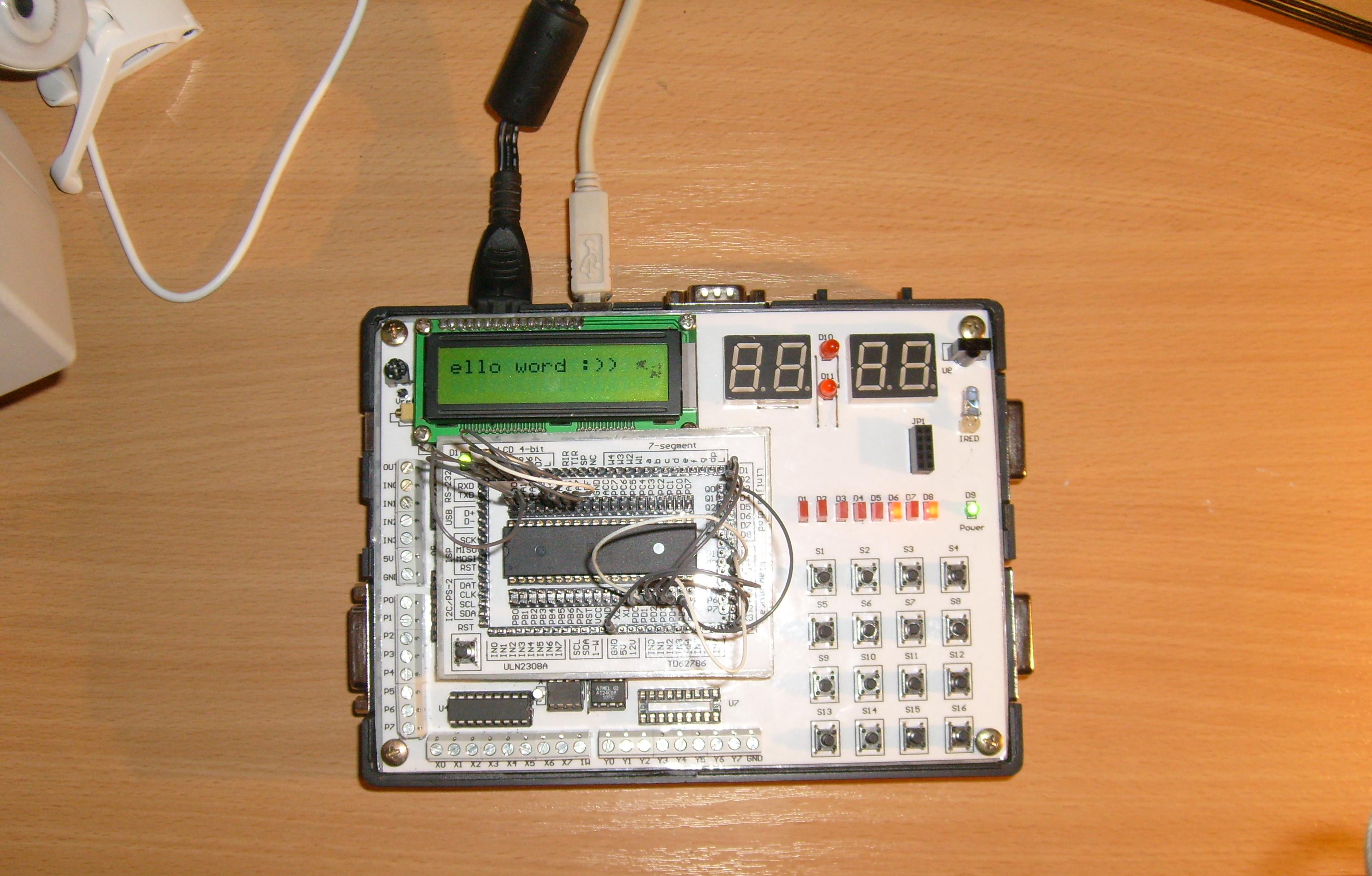
It is a project of a testing plate for AVR. The whole system consists of two sub-systems: uC Programmer and main testing plate.
Construction of main testing plate:
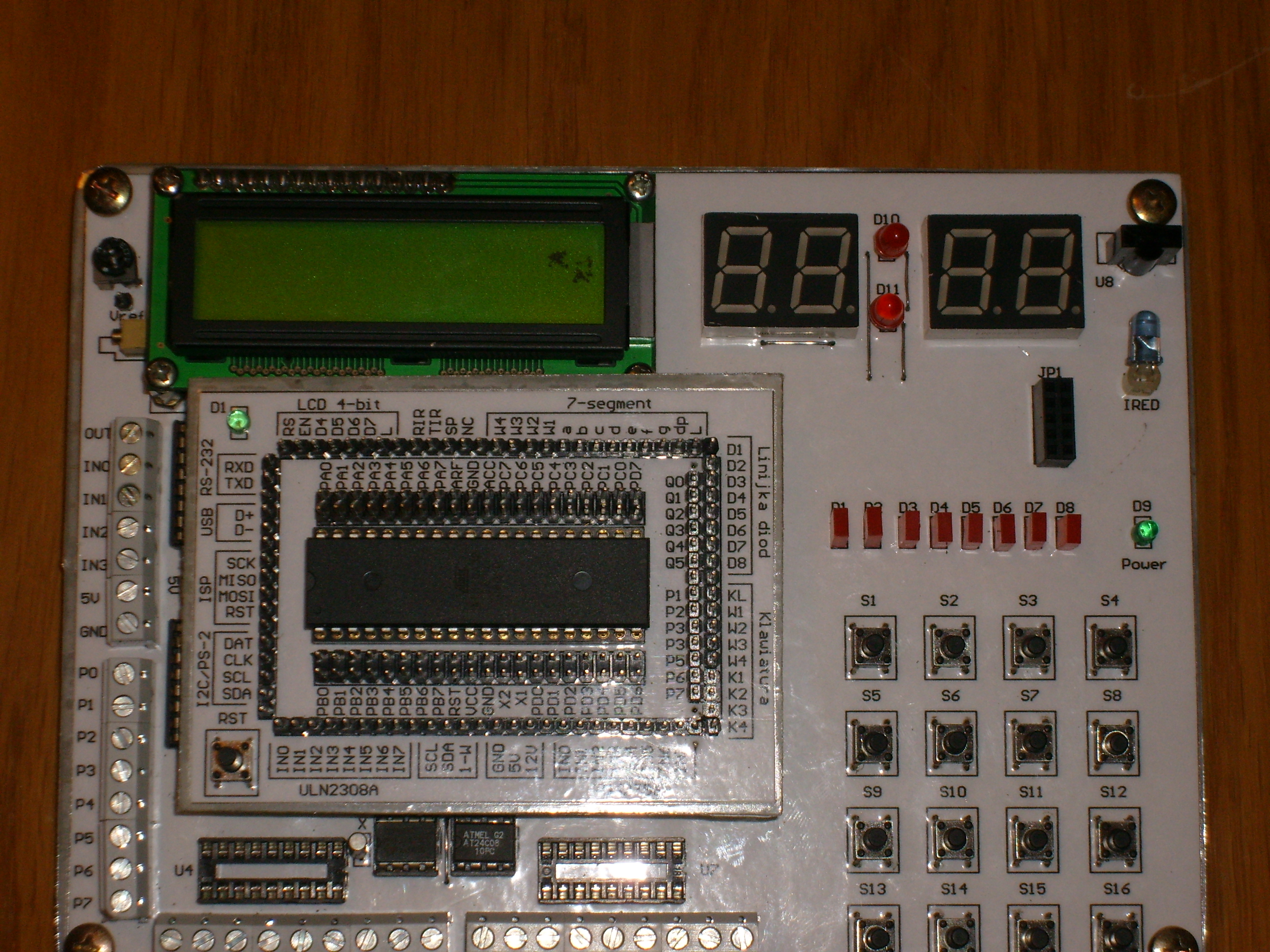
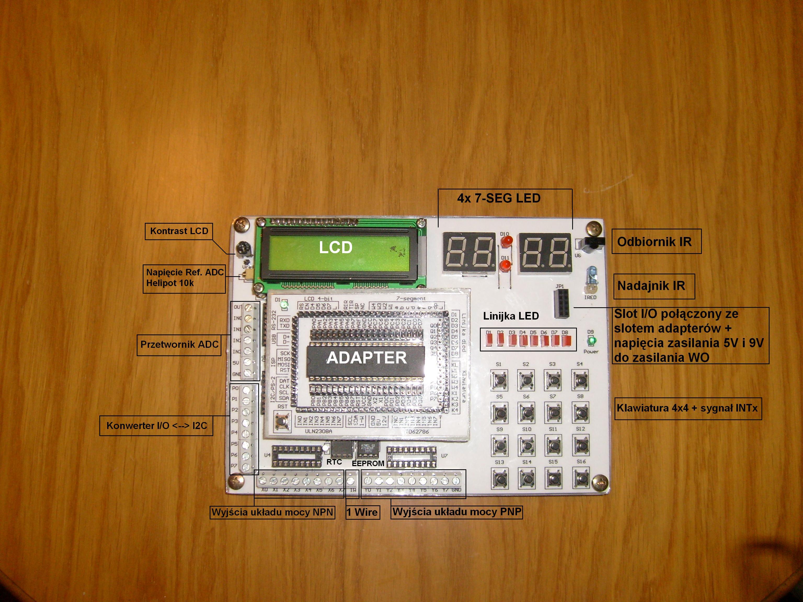
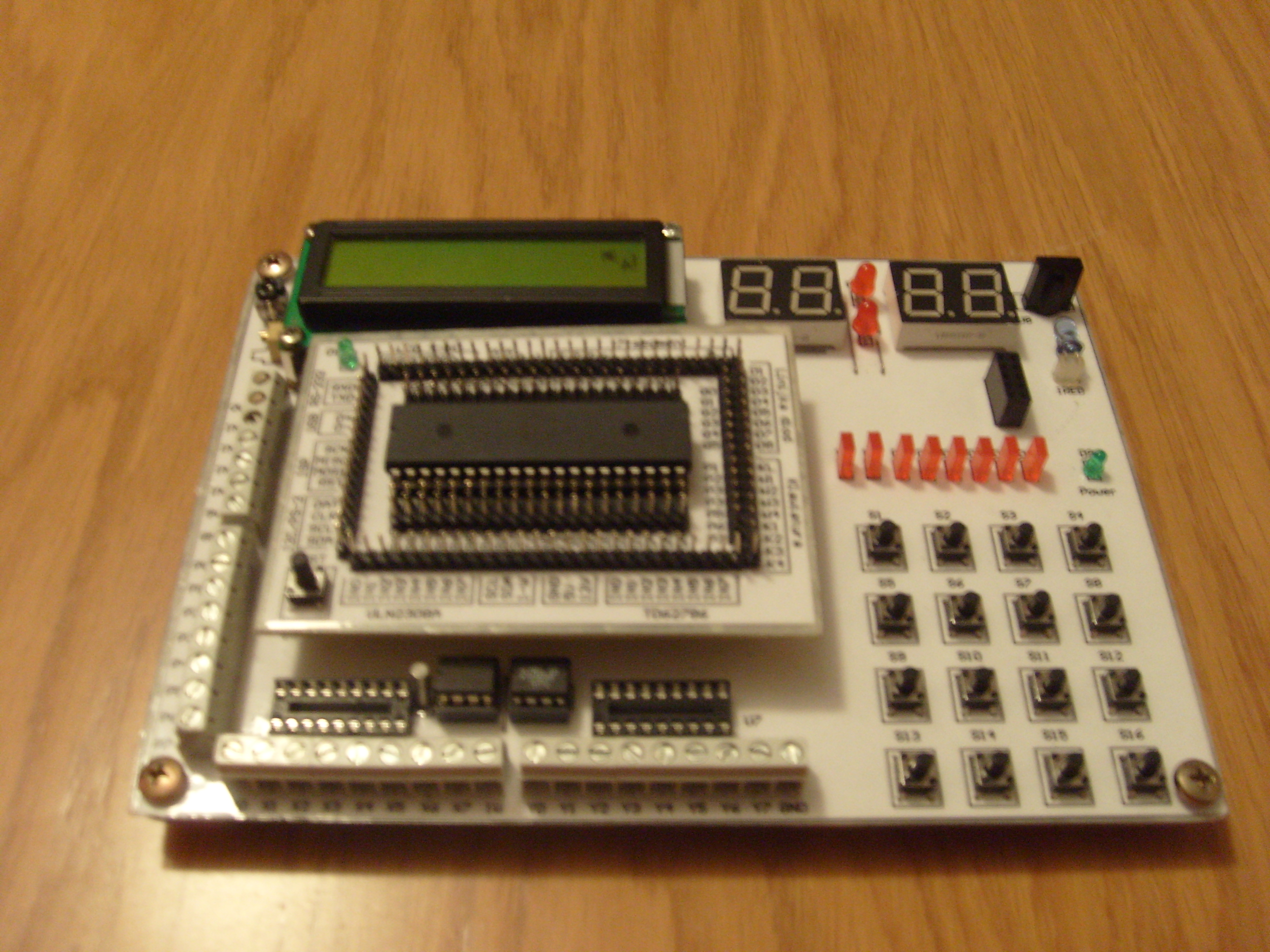
- slot for connecting various adapters with uP
- LCD display 2*16 characters + transistor key for controlling backlight (eg PWM)
- two dual 7-segments displays + seconds LEDs
- transmitter (IR) and IR receiver (TFMS)
- slot for connecting mini-adapters to operational amplifiers, etc. (derived power supply 5V, 9V and few lines connected with adapters with uP)
- 8-bit LED bar
- keyboard 4x4 + additional line connected to INTx uP
- A/D D/A PCF8591 (I2C)
- EEPROM (I2C)
- power implementing systems ULN2803 and TD62786 (NPN and PNP tips)
- real-time system PCF8583 (I2C)
- bi-directional converter I2C/8-bit PCF8574
- 1-wire connector
- adapters → Atmega8, Atmega16/32, Attiny2313 (with descriptions of pins)
- USBasp programmer connected to the main plate and adapter slot
- additional USB port
- PS2 port
- converter MAX232 → connected to the main plate and adapter slot
- two I/O ports (DB15), which enable to connect a second system of test plate or I/O card with executive power systems
- programming multiplexer → allows to switch ISP signals from the main plate to I/O card to program another uP
- additional bidirectional port (DB15) I/O ↔ I2C with PCF8583 system
- piezo buzzer
- external power supply +5V/+12V + stabilizer on plate + 9V (WO power)
Presentation:
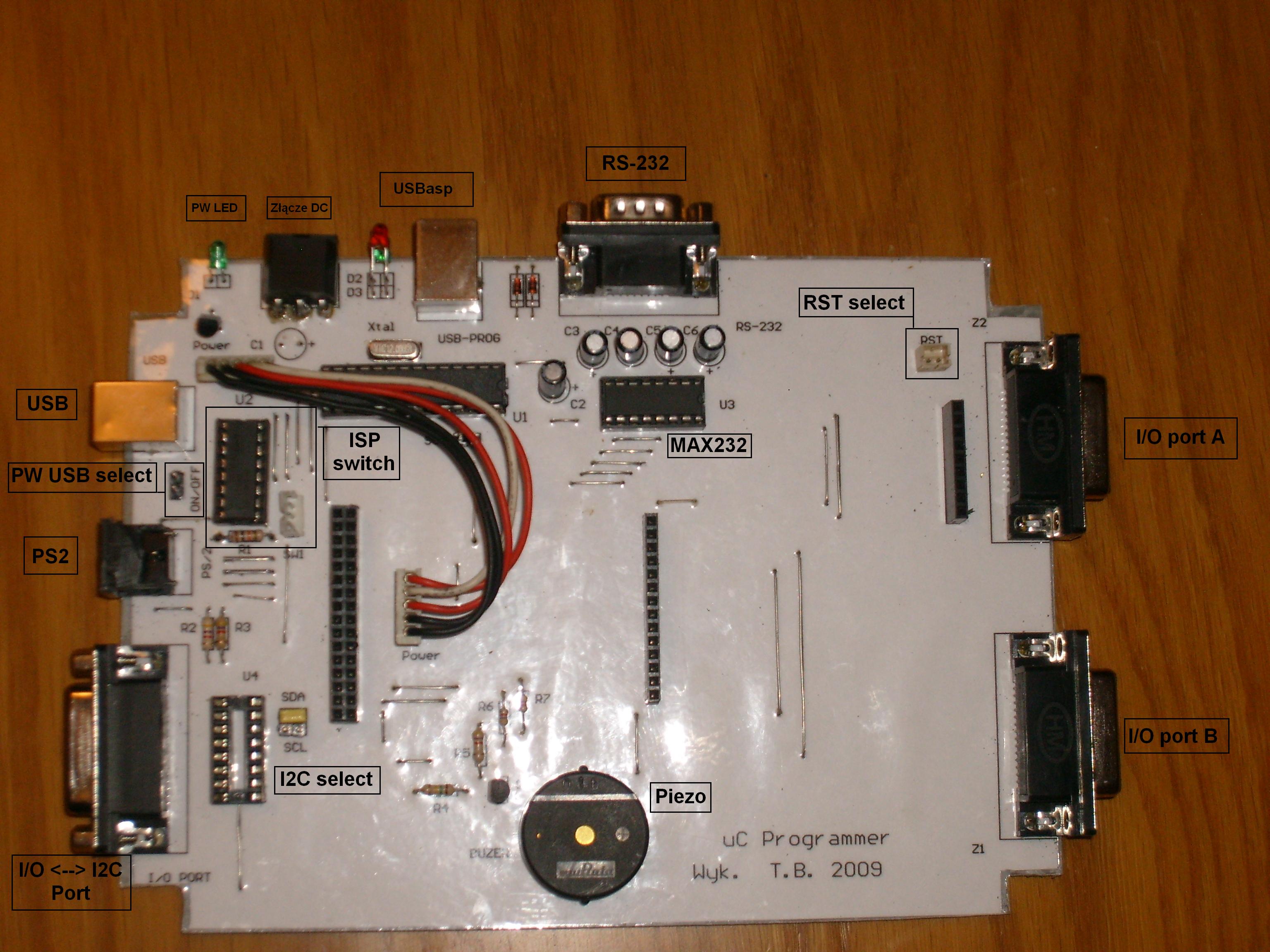
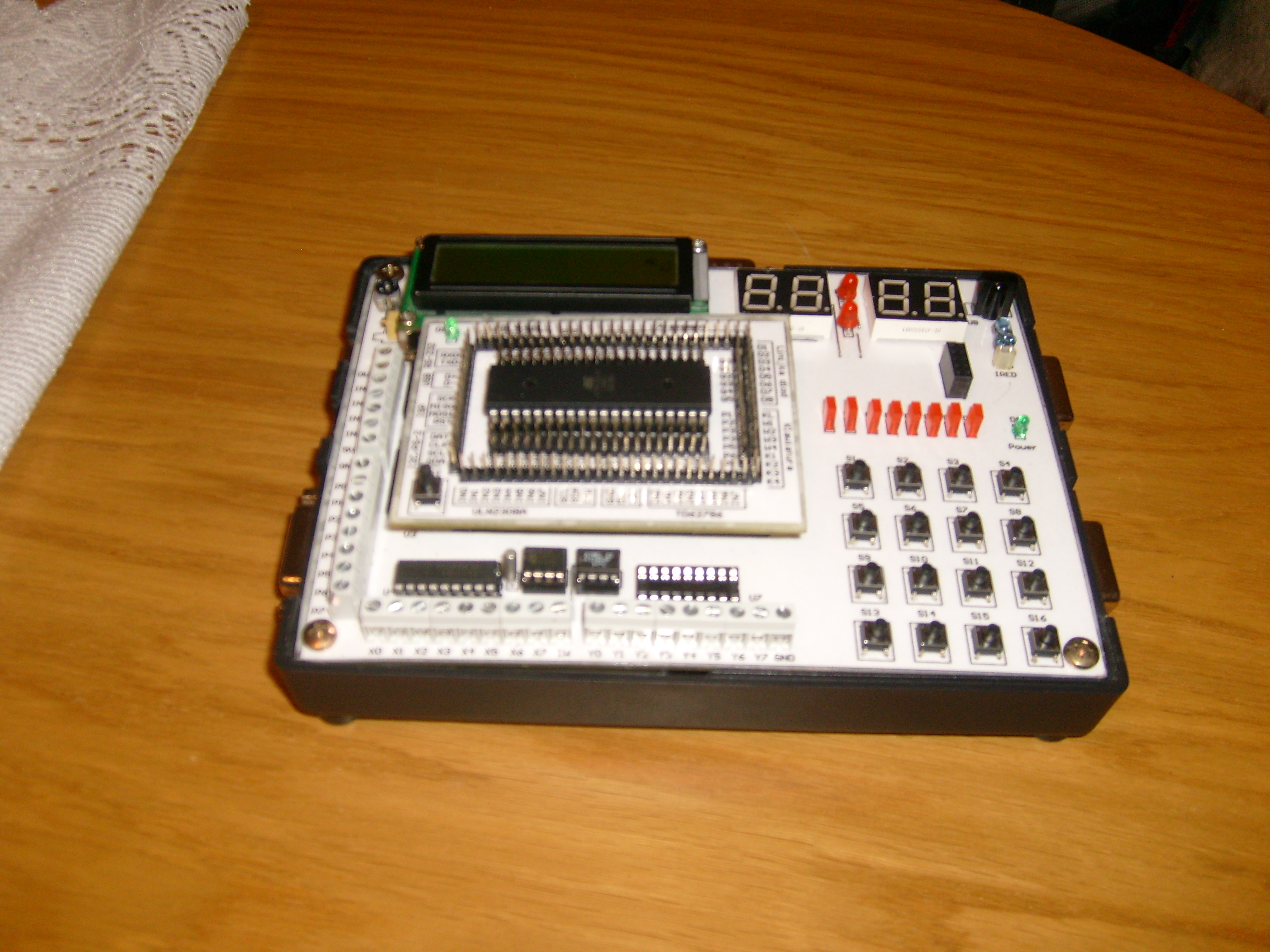
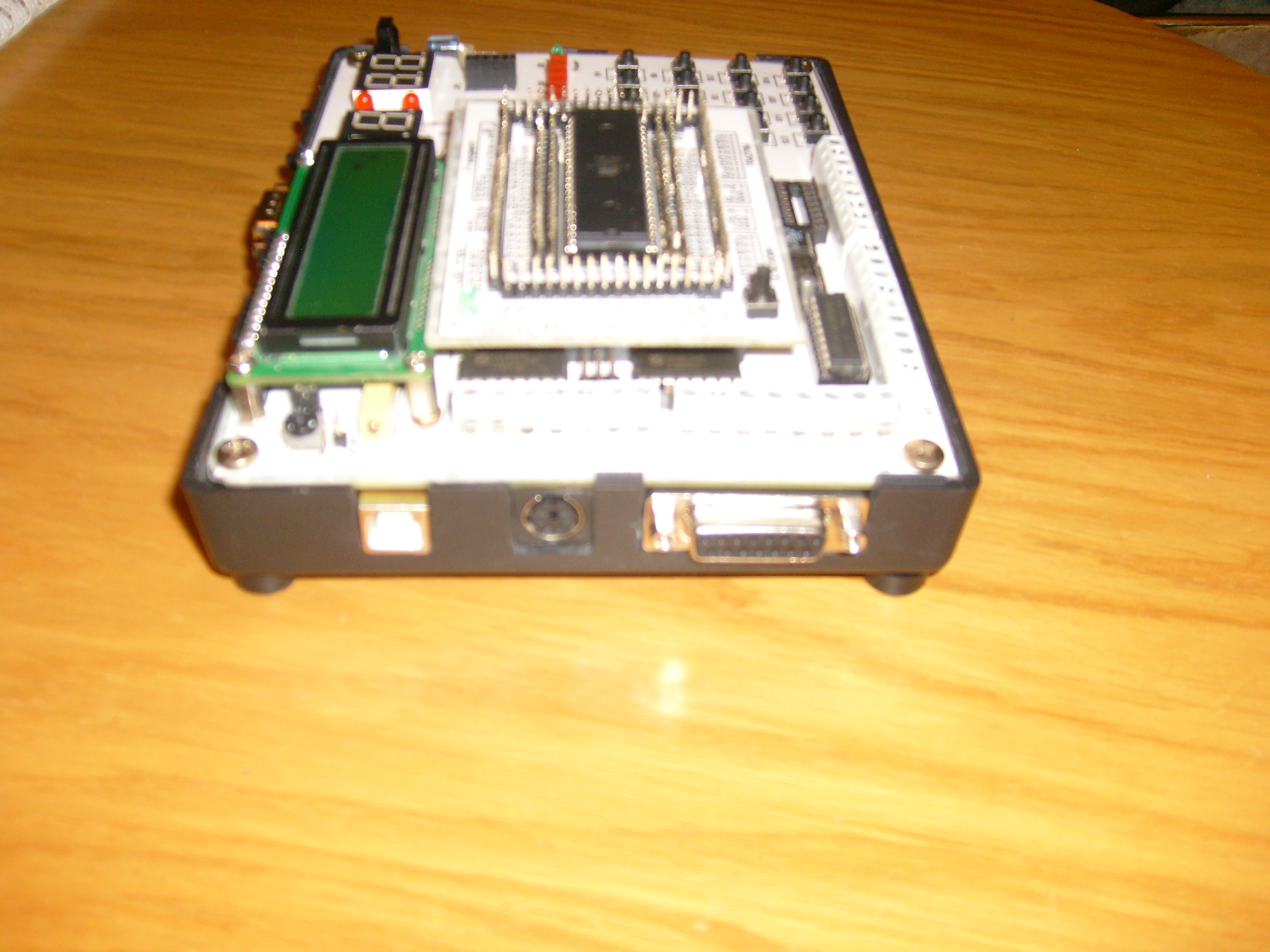
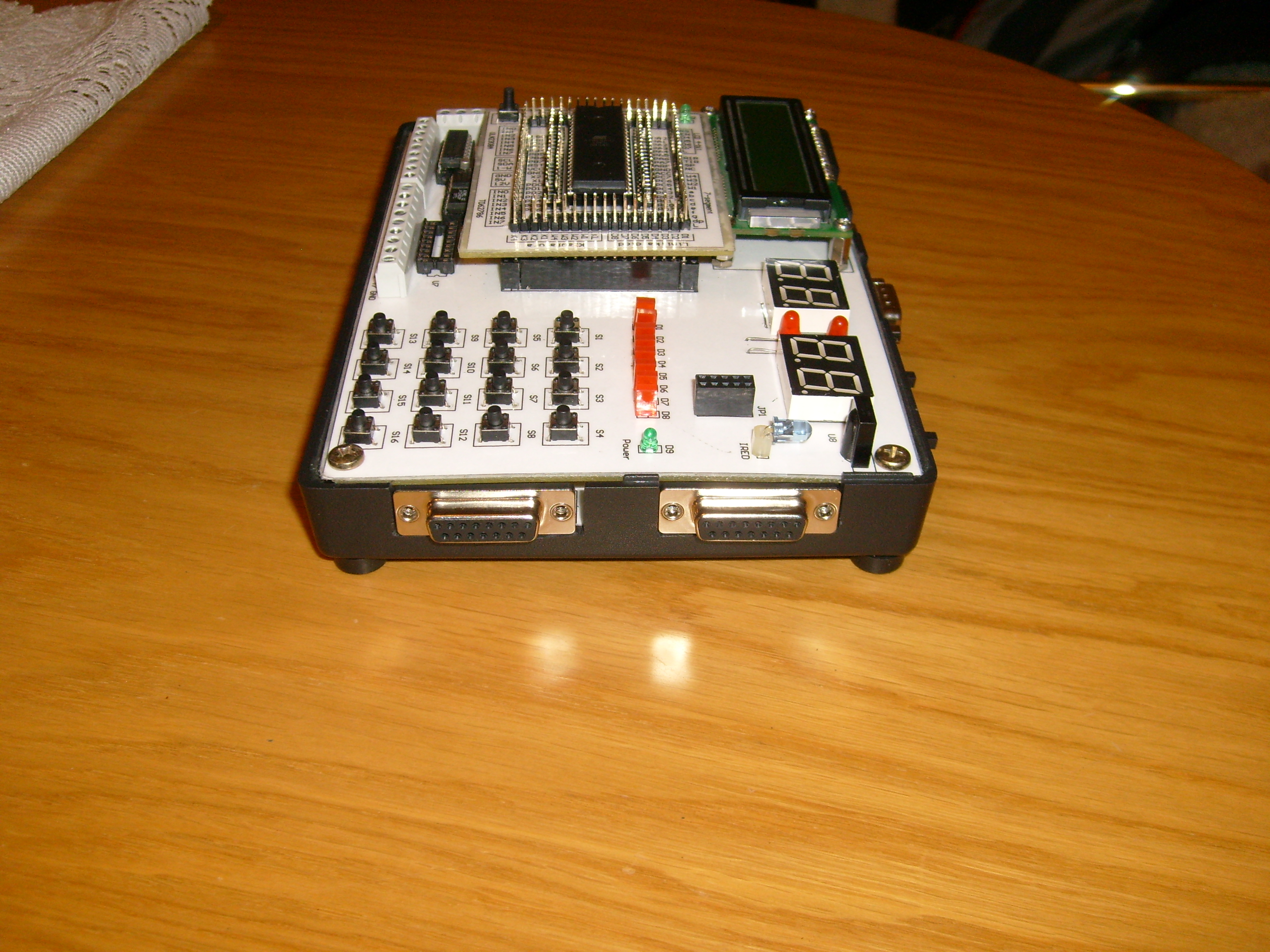
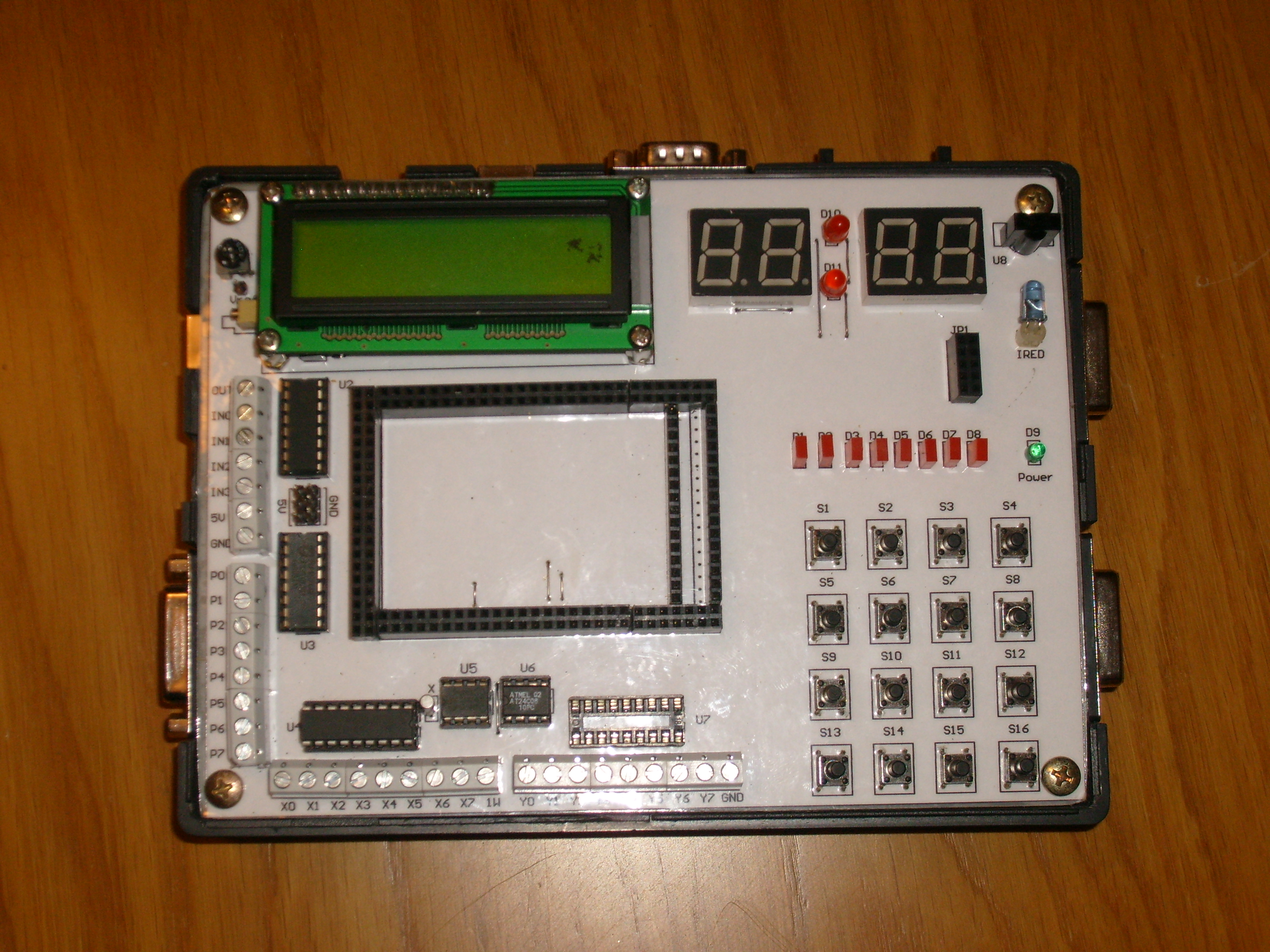
Main plate:
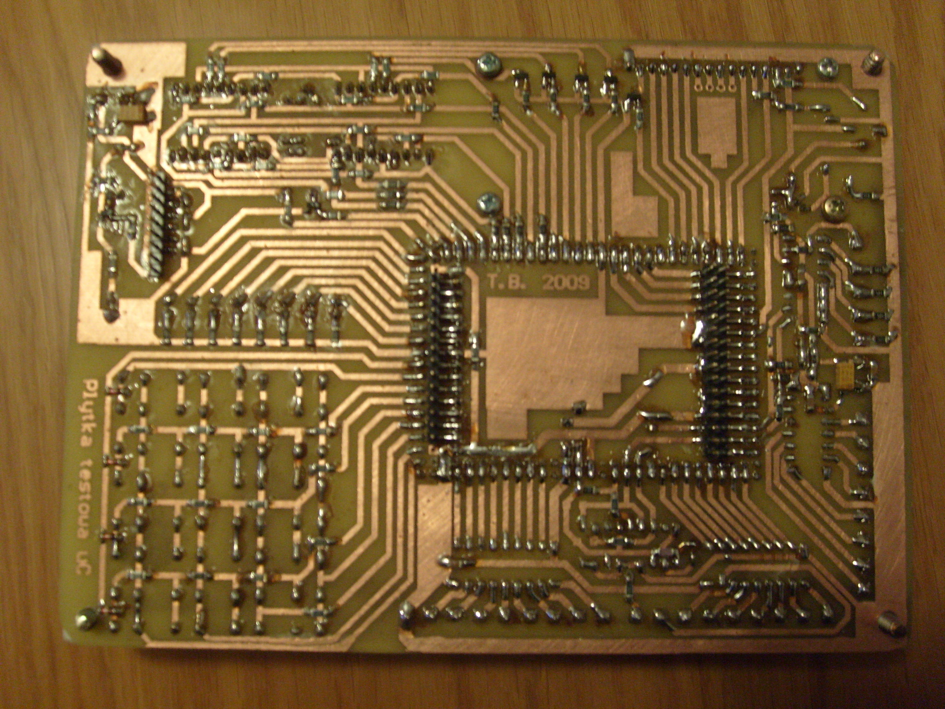
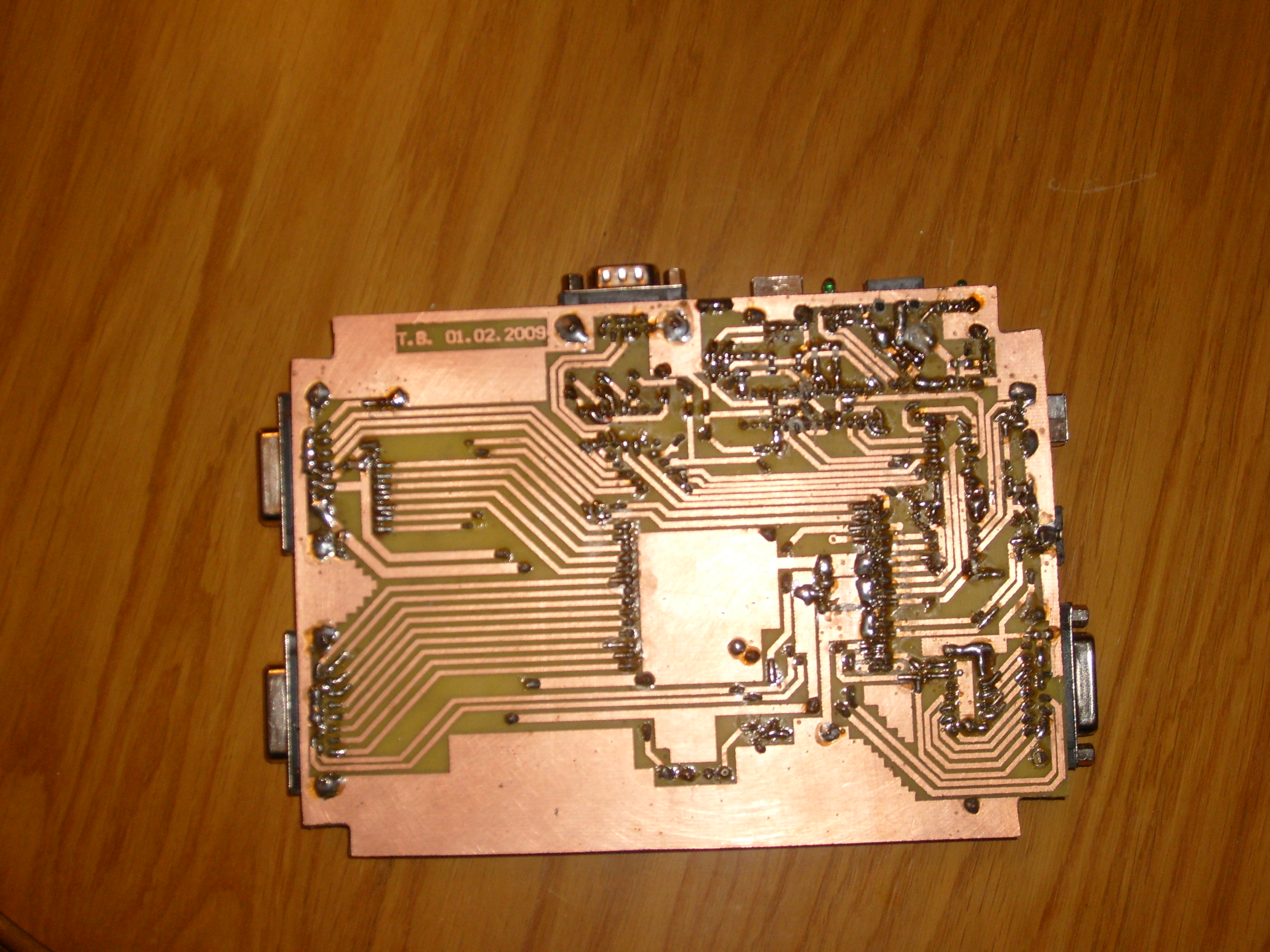
uC Programmer:
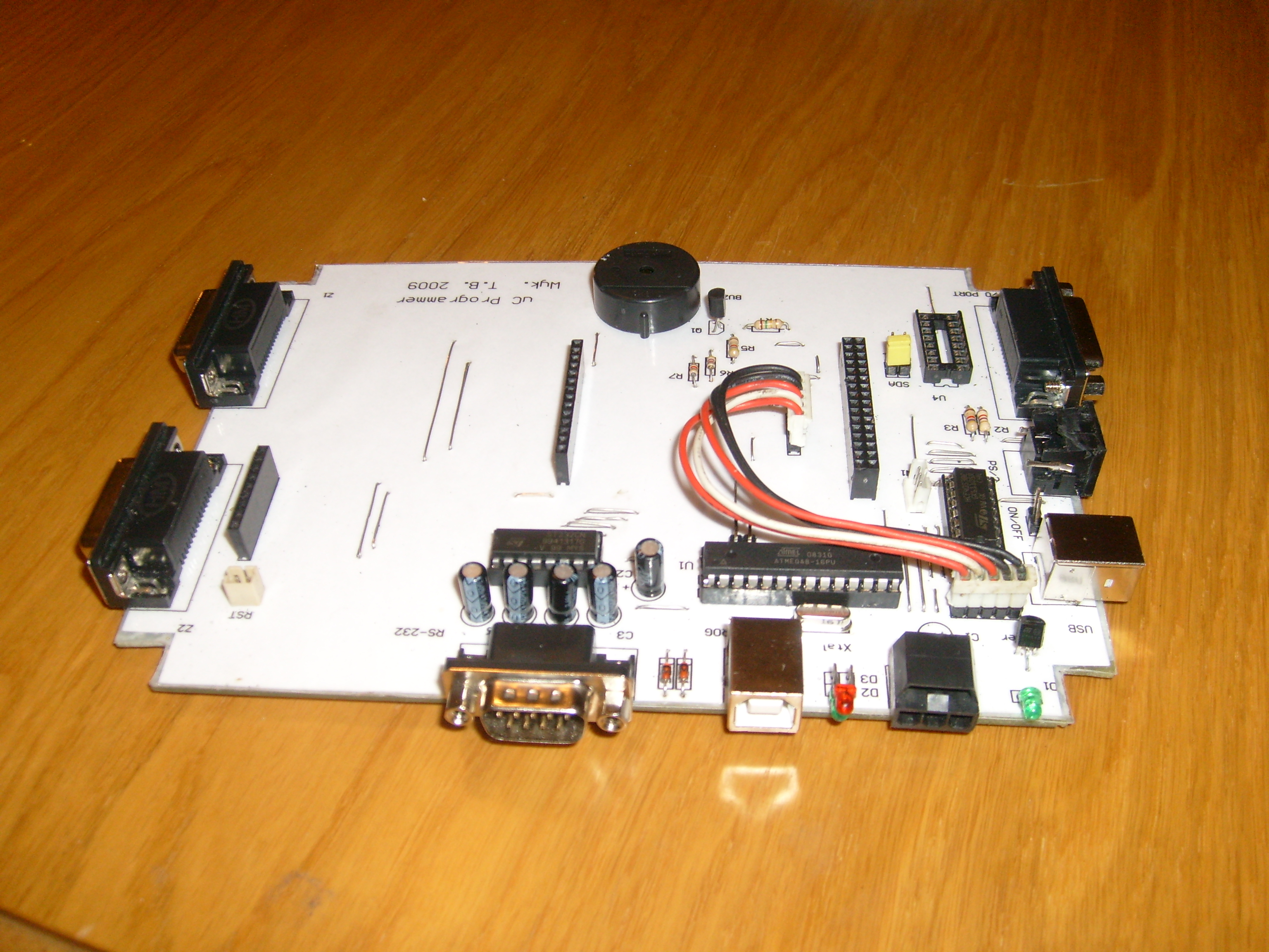
The whole system:

Adapters:

It is an old project. Some modifications could be a good idea:
- plate would be 2- or 4-layer, ordered in a company performing PCB
- fully SMD technology, 0603 housings, etc.
- pulse converters +3,3V/+5V integrated with the plate
- converter USB/RS232 → FT232
- SD card slot
- graphical display, such as Nokia 3510i
- radio adapters
- much thinner signal paths
- processor adapters ARM CORTEX etc. LPC1343 + drivers I/O 3,3/5V
Link to original thread – Płytka testowa mikrokontrolerów AVR v1.1