hosseineslahi7
Junior Member level 1
Dear all,
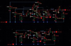
I plan to simulate THD and extract IIP3 of a single transistor by using PSS and PSS+PAC analysis in cadence. I have used the testbench attached below to run simulations. Two bias tees are added to the input and output of the transistor and I have added a resistor of 50 ohm to the gate to match the impedance of the input port in the simulations. The capacitances and inductances are designed for the operating frequency 1KHz. That is why I have used huge amounts. I addition, I repeated the input bias tee and the parallel resistor for two paralllel transistors (as seen in the circuit at the top). Are these testbenches correct or I have done something wrong here?
I appreciate it if you can help me in this regard.
Cheers,
Hossein