Continue to Site

Welcome to EDAboard.com

Welcome to our site! EDAboard.com is an international Electronics Discussion Forum focused on EDA software, circuits, schematics, books, theory, papers, asic, pld, 8051, DSP, Network, RF, Analog Design, PCB, Service Manuals... and a whole lot more! To participate you need to register. Registration is free. Click here to register now.

Termination Technique used in PCB - need details

Status
Not open for further replies.

s.venkatesh

Newbie level 6
Joined
Jun 15, 2007
Messages
11
Helped
0
Reputation
0
Reaction score
0
Trophy points
1,281
Activity points
1,339
Termination Technique

Hi All ,

Please give me the details about the series and parallel terminations used in PCB
what are the necesscity of the terminations used in PCB?
Where we place them ?
please clarify.

Thanks
Venkatesh S
 

Re: Termination Technique

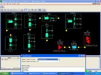
Adding a proper termination is a way to reduce terminations. Different5 types of terminations are
Dual clamp
High Clamp
Low Clamp
RC
Series
Shunt
Thevenin
 

Termination Technique

Basically the terminations are used to avoid the reflection of signals. As per the maximum power transfer theorem, the maximum power will be transfer when the impedance of the both source and destinations (load) are equal. In the case of PCB, the terminations are used to match the impedance. Two types are mostly used: Serial and parallel terminations.

The serial terminations are placed near the source area and parallel terminations are placed near the destination (load).
 

Status
Not open for further replies.

Part and Inventory Search

Welcome to EDABoard.com

Sponsor

Back
Top