Continue to Site

Welcome to EDAboard.com

Welcome to our site! EDAboard.com is an international Electronics Discussion Forum focused on EDA software, circuits, schematics, books, theory, papers, asic, pld, 8051, DSP, Network, RF, Analog Design, PCB, Service Manuals... and a whole lot more! To participate you need to register. Registration is free. Click here to register now.

Synchronous buck converter having output voltage ringing during switching

Status
Not open for further replies.
"There are probably newer seminar papers covering the same topic."

Most likely true.
However, there is something to be said about the old Unitrode app notes...they were classics.
 
  • Like
Reactions: FvM

    FvM

    Points: 2
    Helpful Answer Positive Rating
I have read some snubber design stuff before but I think considering my desired power rating which is 8V input and 4V output, there would be no need to add additional snubber circuits. But after trying four boards with various versions of layout and combination of components, I started to consider the necessity of snubber circuits. Thanks for your help!
 

Something I like to do when designing prototype boards, is to leave placeholders for snubber components.

I leave them at first unpopulated, but if during the testing I see some ringing which requires mitigation, I can add or remove components easily.
 

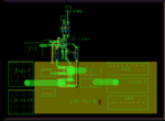
That is great, I would also do that next time. I am attaching my newest layout below, let me know if you have any advice regarding the placement of the components. Note that for this layout, the ringing of the output during switching is much smaller, less than 100mV, but since my following experiments would have a stringent requirement of the ringing, I am still expecting to reduce it to a lower level. Also, I figured that there is also a small ringing in the input with a similar shape as that in the output, any idea about that? Do you think additional input filter needed?
Buck layout.PNG

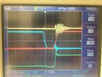
And also a sample waveform, red trace is high gate signal, blue trace is low gate signal, yellow trace is output voltage (AC coupled),and followed by the switching node signal.
Photo Apr 16, 10 12 31 AM.jpg
 
Last edited:

I don't think that you'll achieve much lower switching "noise" without in- and output filters.
 

When you consider what capacitor is best for lowest broadband noise, it is usually advisable to have different types of capacitors in parallel.

For instance, the primary filter may be a tantalum, followed in parallel by a pair of 1 uF ceramics, followed in parallel with several 0.01uF ceramics.
 

Status
Not open for further replies.

Similar threads

Part and Inventory Search

Welcome to EDABoard.com

Sponsor

Back
Top