Continue to Site

Welcome to EDAboard.com

Welcome to our site! EDAboard.com is an international Electronics Discussion Forum focused on EDA software, circuits, schematics, books, theory, papers, asic, pld, 8051, DSP, Network, RF, Analog Design, PCB, Service Manuals... and a whole lot more! To participate you need to register. Registration is free. Click here to register now.

Synchronize multiple sine wave oscillators

Status
Not open for further replies.

Derekk02

Junior Member level 2
Joined
May 8, 2012
Messages
20
Helped
1
Reputation
2
Reaction score
0
Trophy points
1,281
Activity points
1,421
Hi,

I want to build several sine wave oscillators (10k, 20k, 30k)How can I synchronize those oscillators to minimize the phase-shift?
I can make the sine-waves with the MAX038 and use the PDI pin to sync all devices. The thing is that they are very expensive.

Who has another solution?

Regards,
Derek
 

  1. Oscillators can be made synchronous in many ways, including;
  2. PLL phase locked loop
  3. ILL injection locked resonator using 10KHz pulse
  4. Digitally synthesized ( 600KHz clock, /2, /3, /6 then /10 johnson counter with Rsine weighted values summed together)
  5. BPF tuned using 10KHz pulse and then BPF at 10KHz, 20KHz, 30KHz such as Sallen & Keys type. to extract sine with suitable gain.


If phase must be very stable then digitally synthesized is easy and will never drift.
600KHz can even be simple ceramic clock/N for high Q, low drift. or use crystal clock/N, otherwise simple inverter or relaxation feedback clock with CMOS is easy.

Many more ways to do this too. Cost $5.

MAX038 is very custom ASIC for high volume only. dont even think about it.
.
 

Thank you for your reply.
When using a band pass filter with a square wave to the input...I only get odd harmonics right? How do I get 20khz for example?
 

Okay thanks.
Do you have any idea how I can calculate the duty cycle of the pulse so it contains all the necessary harmonics?
 

if 50% only odd
if 10% then harmonics up to 10f .....sinx/x envelope
if 1% then harmonics up to 100f ......
if 0.1% then up to 1000f
but lower amplitude....for each harmonic etc
 

Thanks! I have enough information I think.
:)
 

When designing the band-pass-filter...wich one is the most stable one?
When building the 10 BDF they may have no phase shift relative to each other.
 

Although odd harmonics exist in a mathematical sense in a square wave, they do not run around anywhere inside the square-wave generator for us to 'latch onto'.

The only real instigators in electrical terms that you get are the transitions from lo to hi, or hi to lo.

Therefore to use the bandpass approach, you will still create an LC tank for each frequency you want.

All the tanks are coupled somehow (resistively or inductively?) to the original 10kHz square wave generator.

One tank is tuned to ring for 2 cycles during every cycle of the 10kHz square wave generator. Add a buffer and that's your 20kHz signal.

Another tank is tuned to ring for 3 cycles, to provide your 30kHz signal.

Etc.

The transitions of the 10k generator (from lo to hi, or hi to lo) will provide time markers for all oscillators to fall in step with.

The even harmonics will have a problem because there are instances when a transition will not match the direction of the lead generator's transition. To solve this problem will be a challenge. Come to think of it, you may need to use only the rising edge, or the falling edge, but not both.

Notice that it is easy for a tank to be slightly out of tune. You want it to be compliant so that you can bring it back into step on the next transition. It should be possible to do this by linking it more directly to the lead generator, or by reducing Q, etc.
 
Last edited:

Sallen & Keys is most stable BPF up to Q=100
if Phase coherence is critical then only a digital synth or PLL can do that as I described earlier using 10x,20x, x30 clock.
 

Thank you for the insight!

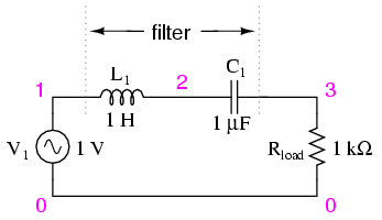
So for example, I can use this circuit to create my BPF with LC-tank ?
02124.png


and then put an buffer/voltage follower at the output of the filter. The challenge is to couple the tanks to the main oscillator to keep them in tune?

Another question. You say that I need an LC tank with the filter. Why would a butterworth filter for example not work?
**broken link removed**

P.s. Sorry for my poor English. Im from germany.

---------- Post added at 00:11 ---------- Previous post was at 00:10 ----------

Sallen & Keys is most stable BPF up to Q=100
if Phase coherence is critical then only a digital synth or PLL can do that as I described earlier using 10x,20x, x30 clock.

Okay. Phase-coherence is critical...though I do not know how critical I need. Only a practical experiment will give me answer to that question. :p
 

LC tank was the concept that first came to mind, as far as being the easiest way to generate ringing oscillations.

You may not have to use coils after all. Anyway you shouldn't have to use a big 1H coil.

The idea is to develop resonating action. To get the odd harmonics, I suppose the bandpass, Sallen-Key, butterworth, etc., filter (using capacitors per your schematic), is a suitable method. There is a certain amount of resonance in these circuits, allowing one frequency to get through.

There is a waveform that contains the even harmonics. Perhaps you can use the sawtooth, because it has only one sharp transition, avoiding the problem mentioned in post #9.

Then one of the above filter designs can be tuned to produce even harmonics.
 

I don't see why the output of analog frequency multiplyers using harmonic filters shouldn't be phase coherent? Existing offset will be constant and can be adjusted if necessary. Also DDS generators use output filters that may show phase dispersion. The discussion could be more practical if you tell about intended phase accuracy and waveform quality.

You specified constant operation frequencies in your initial post. Under this prerequisite, the analog filtering solution sounds realistic. It becomes difficult up to unfeasible if you intend variable frequency.

On the other hand, if you can get to like digital signal generation solutions, they promise a signal quality and phase/frequency precision that's very hard to achieve with analog means. It's effectively a matter of intended performance.
 

Another question. You say that I need an LC tank with the filter. Why would a butterworth filter for example not work?
**broken link removed**

It resembles a single-amplifier multiple-feedback bandpass type. I'm running simulations.

Sure enough, the output gives only one hill/valley per incoming transition.

Hence if you feed it a 10kHz square wave, you can get a 10kHz sine (distorted). It will not give you 20kHz or 30kHz.

So it doesn't look as though a filter per se will suit your purpose. There are configurations which can be modified to a point where provoking it will generate oscillations for a few cycles, then which fade out.

More like a damped 20kHz oscillator, which gets going briefly when triggered by the leading edge from the 10kHz generator. The damping is so it can sync to that leading edge.
 

My basic assumption is that dynamic power dissipation would be the major loss factor. Unfortunately it's not specified for ADG511 or most other analog switches. Due to the low ohmic and respective large area FETs, effective disspation capacitance can be in a 100 pF order of magnitude. 70 Hz sems pretty low, if you can manage this rather low frequency by supplying sufficient large charge pump capacitors, it shoul be O.K.

Another important point is to guarantee break-before-make operation. It's mostly assured for double-throw switches.
 

hi,

can any one please give me why the all digital pll (ADPLL) is most used in digital system that can be then implanted with FPGA technology than aclassical PLL (anlog PLL)

thanks
 

Status
Not open for further replies.

Part and Inventory Search

Welcome to EDABoard.com

Sponsor

Back
Top