Continue to Site

Welcome to EDAboard.com

Welcome to our site! EDAboard.com is an international Electronics Discussion Forum focused on EDA software, circuits, schematics, books, theory, papers, asic, pld, 8051, DSP, Network, RF, Analog Design, PCB, Service Manuals... and a whole lot more! To participate you need to register. Registration is free. Click here to register now.

Synchrbuck converter without reverse current detection exists?

Status
Not open for further replies.
T

treez

Guest
Newbie level 1
Hello,
Have you ever seen a sync buck controller that does not have the facility to detect overly high reverse current flow in the synchronous FET?
 

Where does this overly high reverse current come from ?

How can it be any higher than the peak current through the main upper switching device ?
 
  • Like
Reactions: treez

    T

    Points: 2
    Helpful Answer Positive Rating
Yes, many controllers force the lower FET to conduct negative current. It decreases efficiency at light load but greatly simplifies control loop dynamics. Important when loop bandwidth must be high.
 
  • Like
Reactions: treez

    T

    Points: 2
    Helpful Answer Positive Rating
Yes, many controllers force the lower FET to conduct negative current. It decreases efficiency at light load but greatly simplifies control loop dynamics. Important when loop bandwidth must be high.
All very true.

But how can the synchronous lower fet have an overly high reverse current ?
Whatever current is flowing in the inductor is all there is.
 
  • Like
Reactions: treez

    T

    Points: 2
    Helpful Answer Positive Rating
If efficiency is your top priority, then any negative current is bad, since it's taking energy from the load while dissipating power.
 
  • Like
Reactions: treez

    T

    Points: 2
    Helpful Answer Positive Rating
It certainly takes power from the load, but it returns it to the source when the main upper switching device turns back on.
In effect power flow reverses from load to source, and the buck regulator then becomes bi-directional.
No power is actually lost doing this.

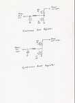
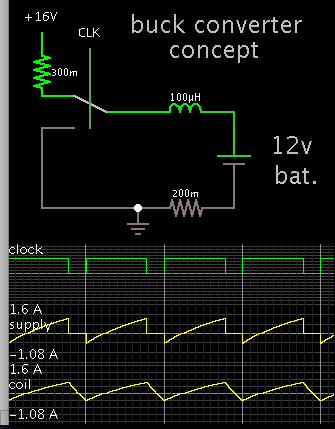
buck.jpeg

Interesting isn't it.
 

If the unit is charging a battery, then the battery can push current down through the lower switch, if the lower switch is left on too long.
 

Brad, it is not a problem.

The choke current will just ramp up in the opposite direction and discharge back into the source without energy loss.
 

Where does this overly high reverse current come from ?
How can it be any higher than the peak current through the main upper switching device ?
The overly high reverse current happens when the output of the error amplifier rails low (eg after an output overvoltage incident caused eg by a full-load-to-no-load-transient whatever) and the output of fet drive pulses to the high side fet stops and goes low…..since the low side sync fet is driven by the “NOT” of the high side FET signal, this then means that the sync FET is held permanently ON…..resulting in overly high reverse current in the sync FET, ..unless there is reverse current sensing in the sync FET.

Page 14 of the LM25115 datasheet explains the problem of overly high reverse current in the synchronous Buck.
https://www.ti.com/lit/ds/symlink/lm25115.pdf
 

Have you ever seen a sync buck controller that does not have the facility to detect overly high reverse current flow in the synchronous FET?
Yes. Many buck converters are just switching the low side transistor unconditionally, in other words implement forced CCM operation. This involves higher losses at low output current but also constant loop gain, straightforward controller design and better transient response.

I previously used TPS40055 sync buck controller, TPS4054 1-quadrant output current version is available alternatively.
 

Brad, it is not a problem.

The choke current will just ramp up in the opposite direction and discharge back into the source without energy loss.

As you say the reverse flow may not subtract much from the supply. However a battery being charged will require a longer time.

This illustrates the synchronous operation I had in mind. The duty cycle is low by only a few percent, enough to create major inefficiency.

3221180000_1452238595.png


The usual feedback mechanisms are voltage sense and current sense. However in this instance, current direction can interfere with proper operation. There needs to be a feedback mechanism which detects reverse flow, and responds by adjusting for a longer duty cycle.
 

It depends on the source impedance.

The worst case might be two very large high capacity batteries of different voltages linked together by a buck converter !

All would be well if the duty cycle ratio is compatible with the voltage ratio.
As the circuit can transfer power in either direction, there is the potential for destructive overload if the duty cycle became extreme in either direction.

A circuit like the above is sometimes used between the +ve and -ve supply rails of a class D audio power amplifier.

The waveforms in the amplifier can be highly asymmetric resulting in not only highly unequal supply rail loading, but the actual shifting of dc power from one power rail to the other.

Its called bus runaway, and can result in some pretty fatal over voltages.

The solution is to have an inductor switched to ground alternatively from -ve and -ve power bus at exact 50/50% duty cycle.

This transfers power directly from the higher voltage bus to the lower voltage bus, thus actively equalising the voltages.

When both bus's are at the exact same voltage power just circulates back and forth without loss.
 
Last edited:

There are several controllers from National (now TI) which have what they call a "diode emulation mode", in which one can actually disable negative current on the bottom Fet, just like a diode.

Like the LM25117.
 
Last edited:

The overly high reverse current happens when the output of the error amplifier rails low (eg after an output overvoltage incident caused eg by a full-load-to-no-load-transient whatever) and the output of fet drive pulses to the high side fet stops and goes low…..since the low side sync fet is driven by the “NOT” of the high side FET signal, this then means that the sync FET is held permanently ON…..resulting in overly high reverse current in the sync FET, ..unless there is reverse current sensing in the sync FET.

Page 14 of the LM25115 datasheet explains the problem of overly high reverse current in the synchronous Buck.
https://www.ti.com/lit/ds/symlink/lm25115.pdf
Okay you're talking about protecting the devices from huge currents, not enforcing DCM to improve efficiency. In certain applications (battery charging, as mentioned before) where the load can store large amounts of energy, this is a valid concern and you may need the controller to limit negative current. I know I've blown some FETs (on both the high and low side) in the past because I was slewing the output voltage so fast that I was getting peak currents 5-10 times the normal steady state amount.
 

It is actually very strange that the TPS40055 (mentioned by FvM above) does not appear to sense for reverse current in the sync FET.
However, the LM25115 definetely senses for reverse current in the sync FET, (even if load is not a battery or big storer of energy) and the LM25115 (datasheet page 15) gives a pretty compelling reason why sensing for overly high reverse current in the sync FET is always necessary in a sync buck. (whatever the application)

LM25115 datasheet
http://www.ti.com/lit/ds/symlink/lm25115.pdf

TPS40055 datasheet
http://pdf.datasheetcatalog.com/datasheet2/0/01oc5r2pkzyqqka8dxucw20ay6ky.pdf

If the LM25115 must have sensing for overly high reverse current in the sync FET, then why does the TPS40055 not have it?
 

It is actually very strange that the TPS40055 does not appear to sense for reverse current
I don't think it's strange, it's sufficient for many or even most synchronous buck applications which don't involve a risk of "overly high reverse current".
 
  • Like
Reactions: treez

    T

    Points: 2
    Helpful Answer Positive Rating
but surely any sync buck has an output capacitor, which as page 15 of LM25115 datasheet says, can provide the DC to give the overly high reverse current on the sync fet.
 

Only if the control circuit is badly designed... Never experienced this problem with usual power supplies.
 
  • Like
Reactions: treez

    T

    Points: 2
    Helpful Answer Positive Rating
what about when the error amplifier output is railed low (as I discuss in post#9 above)....As you know, when the error amplifier is railed, the control feedback loop is not actually operative.
 

This is not a common problem, its certainly possible, but not something that is likely to occur in most applications,

If your error amplifier is suddenly saturating, in the direction of minimum output, that begs the question, why is it doing that ?
 
  • Like
Reactions: treez

    T

    Points: 2
    Helpful Answer Positive Rating
Status
Not open for further replies.

Similar threads

Part and Inventory Search

Welcome to EDABoard.com

Sponsor

Back
Top