Continue to Site

Welcome to EDAboard.com

Welcome to our site! EDAboard.com is an international Electronics Discussion Forum focused on EDA software, circuits, schematics, books, theory, papers, asic, pld, 8051, DSP, Network, RF, Analog Design, PCB, Service Manuals... and a whole lot more! To participate you need to register. Registration is free. Click here to register now.

Switching power supply emission the electromagnetic waves

Status
Not open for further replies.

konkot

Newbie level 2
Newbie level 2
Joined
Jun 21, 2018
Messages
2
Helped
0
Reputation
0
Reaction score
0
Trophy points
1
Activity points
30
Whenever i turn on my computer, the radio is being jammed
i known the reason is the switching power supply inside the computer
when it work, it emission the electromagnetic waves
My question is:
- What is the electronic component of the power supply make the emission
- If i use a power supply with higher capacity, is the emission decreased?

thanks a lot
 

Hi,

- What is the electronic component of the power supply make the emission
* bad PCB layout
* inductors
* wiring
usually it´s not a single component that is responsible for EMI

- If i use a power supply with higher capacity, is the emission decreased?
Maybe, maybe not. It depends on EMI of the whole power supply.

Usually (modern) power supplies should comply with EMI/EMC rules and thus should not jam your radio.

Klaus
 

EMI Generation in SMPS mainly in

1) Transformer/inductor
2) Switching element
3) PCB track connection between high frequency current sink and current source
4) loop of output output rectifier and filter capacitor

If you go with higher power supply, one advantage is the level of EMI will reduce but you can't eliminate the EMI
 

It is hard to say, it is not as simple as the transformer emitting EMI. Any current that form a loop will emit EMI, just like loop antenna. High speed current spike make it that much worst. PCB layout play a vital part in EMI emitting. Ground plane usually help, but still have to be careful not to have cuts in the wrong place. This is a big subject called signal integrity and they actually have engineers specialized in chasing down EMI. It's all electromagnetics.

If you design your own SMPS, you can be in control and if you know what you are doing, it's really not bad at all. BUT if you buy OEM product, then you are really at the mercy of the vendor. I was the manager of EE for semi-conductor analytical instruments, design a few of those like time of flight mass spectrometer. They used to use rackful of analog power supplies to avoid noise. I went in the completely changed them to SMPS, the rack shrink down to a rack mount box. But careful work on the layout of pcb, we did not have a hint of problem in noise in the system. We ran into problem in CE test and mostly chased down to those OEM SMPS. We designed a lot of HV SMPS ourselves because of the requirements, we used them in the most sensitive places and never have problem.

So, I don't think anyone can really answer your question, it's all on the design. I can only say, the transformer is NOT the only problem....not even the major problem. I would be more worry about the MOSFET driving the transformer, the Source of the MOSFET where a lot of current dumping into the ground. It's all about the layout of the pcb. get a book on Signal Integrity. This is one of the book I used, easy to understand, like reading a story book. It wrote in very simple way, mostly avoid the deep EM theory.

https://www.amazon.com/High-Speed-Digital-Design-Handbook/dp/0133957241/ref=sr_1_2?s=books&ie=UTF8&qid=1529734824&sr=1-2&keywords=howard+johnson+in+books
 
  • Like
Reactions: konkot

    konkot

    Points: 2
    Helpful Answer Positive Rating
i known the reason is the switching power supply inside the computer
Not necessarily. If you see FM interferences, it's more likely the computer main board, graphic card or display.
 
  • Like
Reactions: konkot

    konkot

    Points: 2
    Helpful Answer Positive Rating
There is also another possibility, the SMPS is unstable and oscillate. Don't laugh, it is more common than you think. That's the reason they specify minimum load current and if you go below, it gets noisy. Those all just oscillation!!! The power supply is conditionally stable only.

SMPS is actually a closed loop feedback system, one has to design it as such to guaranty unconditional stable, not just slap some caps on the output. Also, most SMPS cannot take too much capacitors at the output or it starts to oscillate ( noisy).

I worked on a military gun camera. The image was noisy, two different group of engineers worked on it and failed. They dumped it on me. I worked on it in term of Signal Integrity, it did not help, so I started looking at the two SMPS chip power supplies using Linear Tech IC. BOTH WERE OSCILLATING. It was not my design, but the design followed EXACTLY the application circuit given by Linear Tech. Linear Tech even gave the part number for each component like the inductor and all. The design followed the application circuit to the "T" and both oscillate!!! I fixed that and it's dead quiet.


Don't think just because it's a commercial product and it got to be good. They are human just like us, we make mistake, that's why we have so many flaky products.

If it is OEM products, I don't know what you can do. This might not be an easy fix. Design is easy, make it behave is engineering.
 
  • Like
Reactions: konkot

    konkot

    Points: 2
    Helpful Answer Positive Rating
Is that radio is battery powered or line powered ? This question should be asked first..
Then we can identify the problem.
 
  • Like
Reactions: konkot

    konkot

    Points: 2
    Helpful Answer Positive Rating
well it may well be that you can stop the interference by increasing the gate drive series resistor....this makes the drain transition time that bit longer.

When i was in a lab once.....i had 1R in the gate series resistor place.......and when i switch on..the lab radio turned off!!!.......so then i increased the gate series resistor to 4R7 and the lab radio was then not affected.

Just remember that when you increase the gate series resistor you also increase switching loss.
 

It is hard to say, it is not as simple as the transformer emitting EMI. Any current that form a loop will emit EMI, just like loop antenna. High speed current spike make it that much worst. PCB layout play a vital part in EMI emitting. Ground plane usually help, but still have to be careful not to have cuts in the wrong place. This is a big subject called signal integrity and they actually have engineers specialized in chasing down EMI. It's all electromagnetics.

If you design your own SMPS, you can be in control and if you know what you are doing, it's really not bad at all. BUT if you buy OEM product, then you are really at the mercy of the vendor. I was the manager of EE for semi-conductor analytical instruments, design a few of those like time of flight mass spectrometer. They used to use rackful of analog power supplies to avoid noise. I went in the completely changed them to SMPS, the rack shrink down to a rack mount box. But careful work on the layout of pcb, we did not have a hint of problem in noise in the system. We ran into problem in CE test and mostly chased down to those OEM SMPS. We designed a lot of HV SMPS ourselves because of the requirements, we used them in the most sensitive places and never have problem.

So, I don't think anyone can really answer your question, it's all on the design. I can only say, the transformer is NOT the only problem....not even the major problem. I would be more worry about the MOSFET driving the transformer, the Source of the MOSFET where a lot of current dumping into the ground. It's all about the layout of the pcb. get a book on Signal Integrity. This is one of the book I used, easy to understand, like reading a story book. It wrote in very simple way, mostly avoid the deep EM theory.

https://www.amazon.com/High-Speed-Digital-Design-Handbook/dp/0133957241/ref=sr_1_2?s=books&ie=UTF8&qid=1529734824&sr=1-2&keywords=howard+johnson+in+books

Thanks for your response
So my question is: What is component of the power supply emitting EMI the most ?
If i use a power supply with higher capacity, is the emission decreased ?
 

Hi,

Thanks for your response
So my question is: What is component of the power supply emitting EMI the most ?
If i use a power supply with higher capacity, is the emission decreased ?

It makes no sense to ask qusetions if you don't read our answers.

Klaus
 

The thing in the SMPS which can cause the most EMI emission is that resulting from the FET drain transitions....fast FET drain transitions (FAST fet switching) causes the greatest EMI emissions.
 

You asked about SMPS, I answer only on the SMPS. But if you look at the computer as a system and treat it as a black box, then you can step by step trying to pin point the problem. I assume you don't want to get into the guts of the computer. Then this is a few steps that you can try on the outside.

Let's assume the EMI emits out, the question is where from the computer. It got to come out from somewhere through cables etc. You have

1) cable to monitor.
2) cable to power plug.
3) USB cables.
4) Speaker cables.
5) From the case.
6) Others.

I would first unplug cables one by one ( of cause not the power cable) ON the computer side. See whether this reduce the interference.

Make sure your case is well grounded.

Power cable is a little tricker. We use clip on torroid and put two turns of the power cable through the torroid on the computer side.

A lot of the monitor cables already have build in torroid, you can follow the cable and you should see whether it has the torroid.

Cross your finger that you can find something following these few easy steps. If one particular cable causing the problem, look for split torroid clips and put the cable through the torroid and wind like 2 turns. See whether this will reduce the noise. This is literally putting a Common Mode Choke on the cable.

Beyond that, there are very few scenarios ( stressing very few) that you can have a quick fix.

Of cause, at any given point, you can try another radio!!!! Not all radio created equally!!!


EDIT: Using a bigger supply is exactly what you DON'T want. remember I said a lot of SMPS has minimum current draw requirement, below that, the supply start to be unstable and you can see the pulse width jitter ( oscillation). You want to run the SMPS at optimal load.
 
Last edited:

Short answer: No it won't. The culprit is the design of your SMPS which makes it radiate EMI and interfere with your radio. Buying a higher quality one from a better brand woould solve the problem as higher quality SMPS have to pass EMI/EMC regulations which are there to ensure that consumers don't face the exact problem that you're facing. Usually a crude option is to enclose the SMPS in a metal casing, but its again not that easy as some of the noise generating sources need to be grounded on the metal case.
TL;DR: No, buy a better supply , not a bigger one.
 

i worked in one place where i designed a 50w led driver.........it fed off an offline 48vdc output psu. It had a 1r gate resistor on the fet......when we switched it on...the lab radio turned off!!.........the lab radio on full blast literally went silent......so we increased the gate resistor to 4r7....and it was problem solved.....i tell thee, i tell thee now....that the biggest noise causator in an smps is a fast fet swith on....and fast fet switch off......slow up that fet and you decrease emi....but at the expense of more switching loss.
Of course i am talking hard switchers here..not resonant...but even LLC does not always switch totally smoothly esp if away from f(upper)...
 

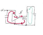
I thought from the beginning the transformer is likely not the problem, the FET and the driver is likely the problem. Problem is most of the SMPS I've seen never have a ground plane, the current loop likely enclosed a certain area. As seen in the picture here:

**broken link removed**

I drew the current path in RED. When switching the FET on, the current is sourced from the reservoir capapacitor through the driver IC to the gate of the FET through the ground back to the other side of the cap. The input capacitance is a few nF and if switch in a few nS, current spike is very high. If there is no ground plane AND particularly if the filter cap is far from the driver IC, the current loop formed by the power trace to the IC, IC output to FET and source of the FET to the ground back to the filter cap can form a pretty big loop and the flux can be quite high.

The other pathe shown in GREEN can cause problem, but I don't think it's as bad as the transformer is an inductor in all respect, dI/dt is slow relatively. But if the GREEN loop is large, that can cause problem also.

Ground plane can solve a lot of these problems. Unlike what people think, from electromagnet theory, the current path follows the path of least inductance instead of path of least resistance.....which is right below the signal trace. ( or I think of it a path of least impedance as the closer the signal and the return, the lower the characteristic impedance, eg strip line or microstrip). So the loop area is only the distance from the signal trace to the ground plane times the length.

Without the ground plane, the only way you can minimize the loop area is have the signal trace right ON TOP of the ground return trace all the way, or else, you create a loop area and emit EMI.
 

Attachments

  • FET current paths.jpg
    FET current paths.jpg
    64.2 KB · Views: 153

now....that the biggest noise causator in an smps is a fast fet swith on....and fast fet switch off......slow up that fet and you decrease emi....but at the expense of more switching loss.

Making the switch slow and inefficient isn't the best way, in my opinion. As Alan pointed out, EMC issues are caused by a fast signal that goes "the wrong way", due to routing and cabling that isn't EMC-aware . So the EMC problem should better be solved by fixing that current path and introducing filters if needed, not by making an inefficient supply with slow switching times.
 
  • Like
Reactions: konkot

    konkot

    Points: 2
    Helpful Answer Positive Rating
Hi,

In detail it is more complicated.
Your gate drive path (red) shows only one situation: charging the C_GS of the Mosfet.
* But another path is gate-source. With it's miller effect.
Then there are the two discharge paths:
* via the GND pin of the driver and source of Mosfet
* via the GND pin of the driver and the source of the Mosfet.
These are four red paths.
And there are transormer primary paths
And transformer secondary paths
You should include in your analysis.

most of the SMPS I've seen never have a ground plane
if the filter cap is far from the driver IC
Hopefully both assumptions are not true for the majority of SMPS...
If they are true... they are a good source of EMI emmissions.


Klaus
 
  • Like
Reactions: konkot

    konkot

    Points: 2
    Helpful Answer Positive Rating
Making the switch slow and inefficient isn't the best way, in my opinion. As Alan pointed out, EMC issues are caused by a fast signal that goes "the wrong way", due to routing and cabling that isn't EMC-aware . So the EMC problem should better be solved by fixing that current path and introducing filters if needed, not by making an inefficient supply with slow switching times.
yes i couldnt agree more, but if you have done all that as much as you can, and still have problems, then slowing up fet switch on is next up on the menu. Certainly slowing the fet up increases switching loss, so yes, its definetely a last resort thing....but often it does come to that i find...As you will know, sometimes the constraints mean you are limited in pcb layers and space etc, and you just cant get the good layout that you want.

- - - Updated - - -

Also, with most hard switchers, there's a certain amount of gate series resistance that you can add that causes pretty negligible extra switching loss...and in my opinion, you should always have at least that much gate series resistance in your gate drive circuit.
-And i say for sure that you should always have a gate series resistor placed on the pcb...even if you end up making it zero ohms.....it absolutely must be included there.

- - - Updated - - -

If i use a power supply with higher capacity, is the emission decreased ?
Not always......eg think of ceramic capacitors where the higher value ones have higher stray inductance.....
You often need low value ceramics right up close to the switching loop to really minimise the loop area to the highest frequencies.

- - - Updated - - -

I never forget testing the ripple voltage on the output of a 1MHz SMPS at a radio company….one reading was with 30uF Cout , and the other reading was with just 6.6uF Cout…….the reading where there was only 6.6uF had less ripple voltage on the output than the one with 30uF on its output…and this was because of the stray inductance being greater with the higher value ceramics used in the 30uF capacitor bank.
The gaffer didn’t at first believe me and was going to sack me for suspected incompetence. I then sent him the impedance vs frequncy graphs.
One of the senior engineers had trashed my hide over it, and was scoffing humble pie when he realised the reason.
 
  • Like
Reactions: konkot

    konkot

    Points: 2
    Helpful Answer Positive Rating
Hi,

In detail it is more complicated.
Your gate drive path (red) shows only one situation: charging the C_GS of the Mosfet.
* But another path is gate-source. With it's miller effect.
Then there are the two discharge paths:
* via the GND pin of the driver and source of Mosfet
* via the GND pin of the driver and the source of the Mosfet.
These are four red paths.
And there are transormer primary paths
And transformer secondary paths
You should include in your analysis.


Hopefully both assumptions are not true for the majority of SMPS...
If they are true... they are a good source of EMI emmissions.


Klaus

I just show one transition....from low to high transition to turn on the FET, the high to low will go through the ground of the driver. I just want to show the problem of current loop.

Now a days, most of the SMPS are designed in China, I won't hold my breath on ground plane. We designed a lot of custom HV SMPS for our instruments, we always have ground plane and careful in layout. We never have any problem with noise and pass CE straight through, all the problem were mostly from OEM SMPS and sloppy cable making......One time we had problem in CE test, took us a lot of chasing around just to find out the assembler was lazy. The cable shield was supposed to connect directly to the connector shell, but he left 6" ground wire from the shield to tie to the shell instead of trimming it down. He just stuff the extra wire into the shell!!! Caused us 2 hours to find because we measure and the shell was grounded. Out of desperation, I opened the shell and found that. trimmed the wire and pass the CE test!!!


I won't trust any SMPS just because it has a CE stamp. We bought the best like TDK, we had nothing but problem with the OEM SMPS.

Not just ground plane, one has to be careful about the cut on the ground and power plane, if there is a discontinue on the ground or power plane, the current will find another path and cause EMI. People might be careful on ground plane, but use cut power plane. When signal go through a break on the plane, there goes the EMI. It's too long to cover everything possible. I am just very interested in signal integrity. I remember when the company hired a signal integrity expert to give a lecture, all the other engineer were yawning and I was the only one that really interact and ask questions. I just get a high chasing current path and layout of pcb.
 
Last edited:
  • Like
Reactions: konkot

    konkot

    Points: 2
    Helpful Answer Positive Rating
Status
Not open for further replies.

Similar threads

Part and Inventory Search

Welcome to EDABoard.com

Sponsor

Back
Top