Continue to Site

Welcome to EDAboard.com

Welcome to our site! EDAboard.com is an international Electronics Discussion Forum focused on EDA software, circuits, schematics, books, theory, papers, asic, pld, 8051, DSP, Network, RF, Analog Design, PCB, Service Manuals... and a whole lot more! To participate you need to register. Registration is free. Click here to register now.

Struggling to design these Boost Converters.

Status
Not open for further replies.

DT_11

Newbie level 4
Joined
Oct 21, 2021
Messages
6
Helped
0
Reputation
0
Reaction score
0
Trophy points
1
Activity points
53
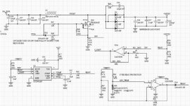
I am designing 2 boost converters, but am going in circles doing so. All design exercises with them I've done gave us a frequency. I've been given nothing of the sort here, so I'm lost.

Circuit 01 Specs:
  • Input voltage of 3.6V.
  • Output voltage of 5V.
  • Output voltage ripple of < 0.5V (< 10% of output voltage with a min load current of 1A).
Circuit 02 Specs:
  • Input voltage of 3.6V.
  • Output voltage of 12V.
  • Output voltage ripple of < 1.2V (< 10% of output voltage with a min load current of 1A).
I feel like I need to choose an NMOS transistor first. I know the drive voltage should be double the output voltage for safety, but am lost on other parameters to look for.

Any help, be it with selecting a transistor or anything to do with this circuit design, is greatly appreciated.
 

there are tons of chips with app notes to get you started here - try reading widely ....
--- Updated ---

5W & 12W respectively, easy ... get stuck into the internet ....
 

Hi,

Do one design first. Start the other after the first is finished.

You talk about Mosfet selection. Why not using a boost controller IC with internal Mosfet?
..or use ready to buy boost modules?

Klaus
 

Hi,

Do one design first. Start the other after the first is finished.

You talk about Mosfet selection. Why not using a boost controller IC with internal Mosfet?
..or use ready to buy boost modules?

Klaus
Ordering a custom PCB is mandatory. What it's of is up to us. I knew the basics of boost converters, so didn't expect to struggle as much as I am. But I'm too far into this circuit as a whole (the boost converter is the final piece of it) to stop now.

I really just don't know where to begin in this design process, I guess. I'm in over my head.
--- Updated ---

there are tons of chips with app notes to get you started here - try reading widely ....
--- Updated ---

5W & 12W respectively, easy ... get stuck into the internet ....
Yeah, today is day 4 of me scouring the internet trying to figure this out. I feel it's mostly the mosfet tripping me up. That, and figuring out the switching frequency of the circuit. If I use a Schottky Diode, I feel like that component's switching frequency would be fast enough that the transistor will end up being what will limit the switching frequency.
 
Last edited:

Hi,

Sadly it seems I was not clear with my question... why not using an IC.

Is it a school project or just for simulation or to build a real circuit?
Does it have to be designed with discrete parts only?

***
From the ripple specification it seems it´s not designed for supplying semiconductor electronics. May I ask what the voltage is used for?

***
You talk about "min current of 1A". So what´s the expectable "max load current"? (even if just for a millisecond)

***
I just want you to focus on these questions. These are application requirements.
No solutions, no PCB, no knowledge...just first steps first

Klaus
It is for an extracurricular through school.

The parts do not need to be discrete. I could use an IC chip. I plan on using pick and place assembly through JLC PCBs, though, due to time (I have about 5-ish weeks left to have a working PCB in hand). This means I have to use their library. They have 3 pages of in-stock mosfets; they have only 3 IC switches. But if one of those will work for this application, I could definitely use it.

Specs don't outline a max load current; the 5V output circuit needs to charge an old smartphone. A 1A output current would probably be best for this. Although, since it's an old phone, we don't care about ruining its battery life - we just need to see that it does indeed charge it.

I appreciate your responses.
 

Hi,
I plan on using pick and place assembly through JLC PCBs, though, due to time (I have about 5-ish weeks left to have a working PCB in hand). This means I have to use their library. They have 3 pages of in-stock mosfets; they have only 3 IC switches. But if one of those will work for this application, I could definitely use it.
Slow down. This is 5 steps ahead. Stay focussed on the requirement.

Specs don't outline a max load current; the 5V output circuit needs to charge an old smartphone. A 1A output current would probably be best for this. Although, since it's an old phone, we don't care about ruining its battery life - we just need to see that it does indeed charge it.
This rather sounds like:
* 1A is the max current, not the min current.
* you rather need a battery_charger than a power_supply_circuit.

Please confirm.

Klaus
 

Hi,

Slow down. This is 5 steps ahead. Stay focussed on the requirement.


This rather sounds like:
* 1A is the max current, not the min current.
* you rather need a battery_charger than a power_supply_circuit.

Please confirm.

Klaus
Yes, this is a portable charger being built. Sorry that I wasn't clear with that before.
1A is the min load current I can test the ripple specs with, according to the specs I'm working within.
 

Hi,

O.K. now we know you need a charger circuit.

Then it´s important to know the battery chemistry (type).
--> please tell us.

Information to this:
The problem is: You can´t just put a 12V voltage to a 12V battery and expect it to be charged properly.
Indeed you always need need to (be able to) charge with higher voltage than the nominal battery voltage.

12V lead acid batteries for example are charged with up to 14.4V.

Every battery type has it´s own reqiurements on charging voltage, charging current, timing temperature, voltage accuracy....
you may have a look at: www.batteryuniversity.com

Klaus
The battery being charged belongs to an iPhone 4s. The original charging cable will be used in conjunction to the circuit I'm building (it will have USB output ports). The 5V and 1A parameters were determined because that's what the iPhone wall adapter's output is: 5V voltage, 1A current. 5W power. So the goal is to have this circuit's output be the same.
 

Hi,

This is so confusing...it´s really hard to find out the real requirements, because you are so busy with thinking currently unnecessary details.

So you don´t open the iPhone and connect your circuit directly to the battery?
Instead you just connect the iPhone to a supply instead of the iPhone´s wall wart.

--> please confirm.

Klaus

Yes, that is correct.

This is the IC I'm thinking about using.
 

You have to define max output current/power to select right solution.
Min current no meaning to select component.

For 3.6V boost to 5V, you have to use some low voltage boost regulator or controller.
If output power is small <10W, it is easy to use monolithic regulator.
If it is higher than 10W, consider using controller. With low input voltage, the controller often use 5V output voltage come back to supply switch driver ... reference to IC: PAM2421AECADJR

For 3.6V to 12V, also have to select IC support min operating voltage < 3.6V and max duty > 70%. Because duty > 50%, the control loop need monitor switching current to regulate correctly. Reference IC: LM3478QMMX/NOPB
Select transistor is not offer for this low voltage input, make higher lost and reduce efficency but easy to drive for some application with input voltage low as 0.6V = ~Vbe ;)
Select Nmos have threshold voltage < minimum input voltage to sure circuit startup successfully. Normally call logic gate mosfet.
For the best choice Nmos is not easy to discuss here. The perfect choice is balance between many parameters and requirements. Example: if select nmos have low Rdson to reduce conduct lost, but turn on/off time will be longer make higher switching lost. If select more powerful external driver or controller that will make high cost. Switching faster to increase efficiency but also make dV/dt higher, make EMI noise higher. Filter noise make higher cost.

I would like to share my boost converter (not meet your requiment but for reference design) use UC3843, Spec: Input 10-35V, Output 36V 80Wmax.
I used it for class-D audio amplifier TDA7498.
 

Attachments

  • boost 36V 80W UC3843 gray.JPG
    boost 36V 80W UC3843 gray.JPG
    85.7 KB · Views: 74

Status
Not open for further replies.

Part and Inventory Search

Welcome to EDABoard.com

Sponsor

Back
Top