Build-A-Burger
Full Member level 1
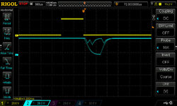
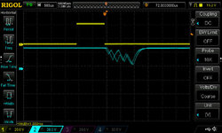
I'm using Atollic True Studio and CubeMX to program a STM32F407 Discovery board and using 1 pin (shown in yellow) to trigger the scope. The signal that's supposed to be TX from the usart doesn't look right. I've tried it powering it with the USB cable and using a separate 5v power supply.
Can't see that I'm doing anything wrong.
Here's the code from usart.c
And here's where I call the usart transmit function:
Can't see that I'm doing anything wrong.
Here's the code from usart.c
Code:
void MX_USART1_UART_Init(void)
{
  huart1.Instance = USART1;
  huart1.Init.BaudRate = 9600;
  huart1.Init.WordLength = UART_WORDLENGTH_8B;
  huart1.Init.StopBits = UART_STOPBITS_1;
  huart1.Init.Parity = UART_PARITY_NONE;
  huart1.Init.Mode = UART_MODE_TX_RX;
  huart1.Init.HwFlowCtl = UART_HWCONTROL_NONE;
  huart1.Init.OverSampling = UART_OVERSAMPLING_8;
  if (HAL_UART_Init(&huart1) != HAL_OK)
  {
    Error_Handler();
  }
}
void HAL_UART_MspInit(UART_HandleTypeDef* uartHandle)
{
  GPIO_InitTypeDef GPIO_InitStruct = {0};
  if(uartHandle->Instance==USART1)
  {
  /* USER CODE BEGIN USART1_MspInit 0 */

  /* USER CODE END USART1_MspInit 0 */
    /* USART1 clock enable */
    __HAL_RCC_USART1_CLK_ENABLE();

    __HAL_RCC_GPIOA_CLK_ENABLE();
    /**USART1 GPIO Configuration
    PA9     ------> USART1_TX
    PA10     ------> USART1_RX
    */
    GPIO_InitStruct.Pin = TX1_Pin;
    GPIO_InitStruct.Mode = GPIO_MODE_AF_PP;
    GPIO_InitStruct.Pull = GPIO_PULLUP;
    GPIO_InitStruct.Speed = GPIO_SPEED_FREQ_MEDIUM;
    GPIO_InitStruct.Alternate = GPIO_AF7_USART1;
    HAL_GPIO_Init(TX1_GPIO_Port, &GPIO_InitStruct);

    GPIO_InitStruct.Pin = RX1_Pin;
    GPIO_InitStruct.Mode = GPIO_MODE_AF_PP;
    GPIO_InitStruct.Pull = GPIO_PULLUP;
    GPIO_InitStruct.Speed = GPIO_SPEED_FREQ_VERY_HIGH;
    GPIO_InitStruct.Alternate = GPIO_AF7_USART1;
    HAL_GPIO_Init(RX1_GPIO_Port, &GPIO_InitStruct);

  /* USER CODE BEGIN USART1_MspInit 1 */

  /* USER CODE END USART1_MspInit 1 */
  }
}
And here's where I call the usart transmit function:
Code:
for(;;)
    {
        vTaskDelay(10);
        HAL_GPIO_WritePin(GPIOB, TRIG_Pin, GPIO_PIN_SET);
        vTaskDelay(1);
        HAL_GPIO_WritePin(GPIOB, TRIG_Pin, GPIO_PIN_RESET);
        ret = HAL_UART_Transmit(&huart1, pData, Size, 100);
        data[0]++;
   }