Alloy
Advanced Member level 4
Hello.
I am making a SSTC (Solid State Tesla Coil). That's a device which converts mains power (directly powered from 230V socket) to high voltage (100kV +).
The halfbridge is made of two IGBTs which are switched at around 200kHz (or less, I might go for 100kHz or so in the end).
I'd like to design my single-sided PCB well but I don't know where to start.
1. Can anyone recommend me any online readings, sites, videos, PDFs or ebooks related to high power/frequency PCB design?
2. Has anyone here designed a halfbridge single-sided PCB for Tesla or induction heater and can share his layout?
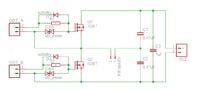
3. Please take a look at my halfbridge schematic and layouts:
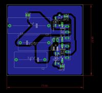
I have made three PCB layouts for this schematic:
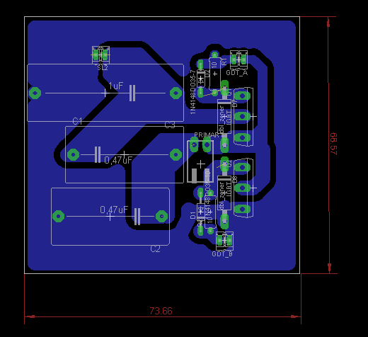
LAYOUT A:
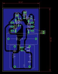
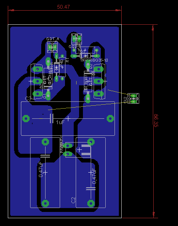
LAYOUT B:
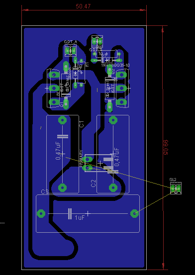
LAYOUT C:
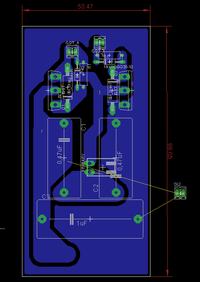
Which one of those PCBs is the best for so far and how can I improve it more? Any suggestions?
Thanks in advance.
I am making a SSTC (Solid State Tesla Coil). That's a device which converts mains power (directly powered from 230V socket) to high voltage (100kV +).
The halfbridge is made of two IGBTs which are switched at around 200kHz (or less, I might go for 100kHz or so in the end).
I'd like to design my single-sided PCB well but I don't know where to start.
1. Can anyone recommend me any online readings, sites, videos, PDFs or ebooks related to high power/frequency PCB design?
2. Has anyone here designed a halfbridge single-sided PCB for Tesla or induction heater and can share his layout?
3. Please take a look at my halfbridge schematic and layouts:
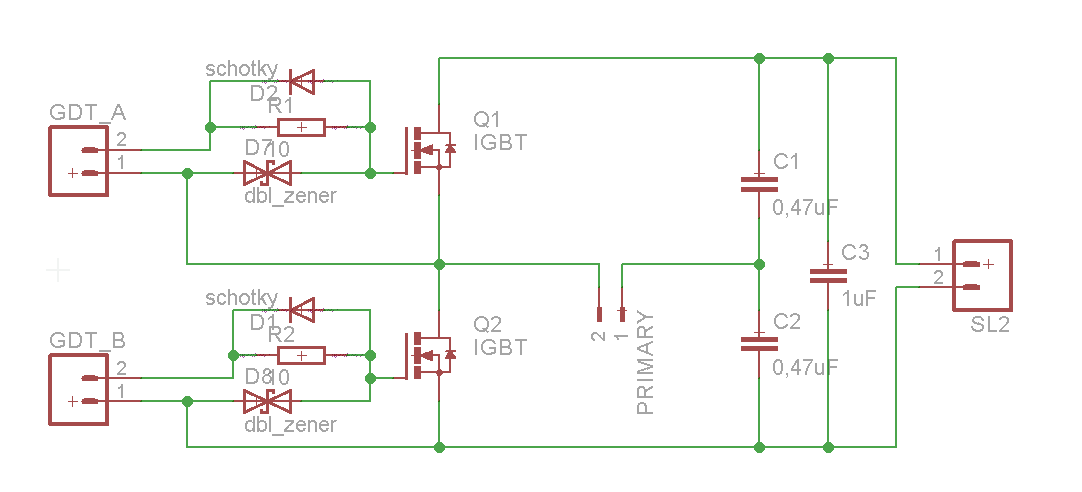
I have made three PCB layouts for this schematic:
LAYOUT A:
LAYOUT B:
LAYOUT C:
Which one of those PCBs is the best for so far and how can I improve it more? Any suggestions?
Thanks in advance.