go2tariq
Junior Member level 3
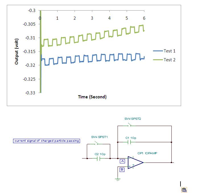
I have a problem I configured my amplification unit as a integrator. As a result I am getting square wave for example see the image file. Could anyone please help me to identify what is hapenning actually.
Thanks in advance.
Thanks in advance.