Continue to Site

Welcome to EDAboard.com

Welcome to our site! EDAboard.com is an international Electronics Discussion Forum focused on EDA software, circuits, schematics, books, theory, papers, asic, pld, 8051, DSP, Network, RF, Analog Design, PCB, Service Manuals... and a whole lot more! To participate you need to register. Registration is free. Click here to register now.

Solving Iout TL431

engr_joni_ee

Advanced Member level 3
Joined
Nov 3, 2018
Messages
750
Helped
2
Reputation
4
Reaction score
4
Trophy points
18
Activity points
6,231
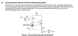
I am considering the attached circuit TL431 as a current source. I am wondering how do we solve Iout ?

I found this circuit at Figure 7 under the link
https://www.ti.com/lit/an/snoaa46/snoaa46.pdf

The datasheet of TL431 can be found from here.
https://www.ti.com/product/TL431LI-Q1/part-details/TL431LIAEDBZRQ1

Iout = Vref/Rs + Ika

If Rs = 100 Ohm
Vref = 2.495 V (according to datasheet)
What is the value of Ika ?

How do we chose R1 ? If depend on Vcc, Iout, hfe, Ika. What is hfe ? Is that related to transistor NPN shown in the circuit ?
 

Attachments

  • Untitled 633.png
    Untitled 633.png
    73 KB · Views: 58
Hi,

one of the rare times that in my opinion the Application note is not of very good quality.
Mainly because:
* there are much more accurate circuits (like replacing a BJT with a logic level MOSFET)
* it is not very explanatory
* it includes errors (If I´m not mistaken the I_Out formula of Figure 8 is wrong, because I_ka is not directly involved)

Btw: still it explains what hFE is. (And IMHO it should be common knowledge for an electronics designer.)

Depending what you need one could give detailed assistance. Basically...
* Figure 7 shows a "2 pin circuit" (VCC, OUT)
* Figure 8 shows a "3 pin circuit" (VCC, GND, OUT)
The 3 pin solution (if possible for your application) is more accurate.
When additionally the BJT is replaced with a MOSFET. ... you get a rather accurate (and simple) I_Out = V_Ref / R_s.
(Stability needs to be checked)

Klaus
 
@KlausST, Ika flows in the load and is not seen in the sense resistor, it could easily be in the range 500uA - 1mA for a standard TL431, or more if the designer allows it
--- Updated ---

Here you go ....
 

Attachments

  • impr curr source.jpg
    impr curr source.jpg
    415.9 KB · Views: 41
Last edited:
Ika flows in the load and is not seen in the sense resistor,
You referred this to me. So I guess you want to correct me. I´m fine being corrected.
I referred the "wrong I_ka" to the formula in accordance of Figure 8. Maybe you missed this.

What do you say about I_ka in formula of Fig. 8? Is it correct?

****
To your circuit.
It is an improvement to the circuit of Figure 7:
But still there is an erroneous current through the lower 19k resistor (node IN-).
This erroneous current is: I_err = (V_out -2.5V) / (23k + 19k)

So
* I_err @ V_out = 12V is 226uA.
* I_err @ V_out = 5V is 60uA.
* I_err @ V_out = 2.5V is 0uA.

With your 1A circuit, the error at 12V (VOut) is just 0.023% and thus negligible.
With the OP´s 25mA circuit (Rs = 100 Ohm, 2.5V) the error is 0.9%

It depends on the application (OP´s requirement) whether this considered good or not.

***
I still vote for the more simple Figure 8 circuit but using a MOSFET instead of an BJT.

Klaus
 
The "19k" is a poor drawing of 10k - apologies - the op-amp is simply x 2.5, Diff amp

the xtor could easily be a darlington ( cheaper and less volts to drive )

I_ka is the current flowing from anode to kathode - it goes straight to the output - and is nòt seen in the sense resistor in the ckt in post #1
--- Updated ---

For the ATL431LI part the OP has suggested, the I_ak min bias is 80uA, which adds to the controlled current in the load - this occurs for BJT or mosfet

so the min error in the original circuit is 80uA, certainly it is easier to drive a mosfet than a plain BJT with these low currents in the top resistor.
 
Last edited:
I_ka is the current flowing from anode to kathode - it goes straight to the output - and is nòt seen in the sense resistor in the ckt in post #1
But in your circuit I_ka does not go straight to the output.
--> You see it´s not very helpful in a discussion when one person refers to the one circuit, and another person quotes the same statement but refers it to a different circuit.

***
10k vs 19k in your circuit:
The 10k makes the error even worse. (independent of XTOR)

Now the erroneous current is (V_out - 2.5V) / 35k.
makes it 271uA @ V_out = 12V

***
I don´t understand the "darlington" comment at all.
What circuit are you talking about?
* Post#1: darlington or not makes no significant difference on output current
* Figure 7: Darlington or not makes no significant diffrence on output current
* Figure 8: (not mentioned in your comments at all) .. here it would make a difference.

I also don´t understand what "less volts to drive" means.

Klaus
 
Correct - in my ckt I_ak does not go to output - hence less error.

Darlington requires 1.2V to just turn it on, mosfet may require 5V, hence less volts to drive a Darlington

The op-amp forms a differential amplifier, if we make the R's 250k & 100k, the error currents are less and the x 2.5 function is more closely met

hope this explains matters.
 
Unlike @KlausST I found the datasheet to be accurate and more than adequate if you follow the app note link for more details. The spec table indicates normal Ika=15ma. 18mA max

Then choose Rk including Iout /50 for a decent NPN hFE or a Darlington for more Iout than recommended. FETs may be used if Vth is low <=1V for the reasons stated in the doc. As conventional FETs are Vth=2 to 4 V threshold and you need 2x Vt for low threshold and 2.5x for conventional Vgs bias. Darlingtons need >1.3V.

1712515972468.png
 
To be serious, I don't understand the controverse. Said Fig. 8 is in the TI application note, not in TL431 datasheet. It's not related to TL431 but LM4041 and erroneously copying a formula from TL431 circuit Fig. 7.

As far as I see, the R1 related formula in Fig. 7 is also wrong because the voltage across R1 is not Vcc. In any case, Fig. 7 is no useful precision current source, as stated by others before.
 
Last edited:

    KlausST

    Points: 2
    Helpful Answer Positive Rating
Hi,

The OP referred to the application note.

And I said, I don´t like the application note, because it includes .. error(s).
one of the rare times that in my opinion the Application note is not of very good quality.
Mainly because:
* there are much more accurate circuits (like replacing a BJT with a logic level MOSFET)
* it is not very explanatory
* it includes errors (If I´m not mistaken the I_Out formula of Figure 8 is wrong, because I_ka is not directly involved)

It´s not that I pulled the AN out of nowhere. I referred to what the OP gave us.
I don´t know why the OP used the circuit of figure#7 ... while in my eyes the circuit of Figure #8 is more suitable for the OP.
So what´s wrong in recommending the - in my eyes - better circuit?

********
As I understand the OP wants an accurate constant current source.
I don´t understand why to use that "sub optimal = non accurate" circuit of Figure 7? I simply can not recommend it.
Also I don´t understand why to do handstands to (only partly) rectify the problems of Figure #7 by using an additional OPAMP.
Using 14 components in post#3. (still less performance than a simple circuit). I also can not recommend it.

There is a simple and accurate 4 devices solution (Figure #8 but using a MOSFET). This is what I recommend.
But as soon as I recommend Figure 8 circuit ... I tink it´s my job to point out that the given formula is wrong (in my eyes)..
and the OP already is worried about I_ka.

Simple 4 devices circuit with almost optimal performance (Way better perfomance than all other solutions shown in this thread)

Focus on the OP`s task. Help the OP to find a simple yet accurate solution.
--> Why make it more complicated? Why make is less accurate? Explain this to the OP, not to me. I don´t need an accurate current source.
And I´m fine if someone can explain that a different solution gives a benefit compared to the Fig 8 MOSFET circuit.

Klaus
 
Last edited:
High side current source with the "other" type of TL431 - the LM4041 - ref in high side: the formula is wrong - the error is only the base

current - replace with P fet - no base current - current is exactly 1v225 / Rs - winner winner - chicken dinner !

1.225 Vref 15V max

1712530918804.png
 
Last edited:
  1. I am considering the attached circuit TL431 as a current source.
  1. I am wondering how do we solve Iout ?
  2. What is the value of Ika ?
  3. How do we chose R1 ?

I found this circuit at Figure 7 under the link
https://www.ti.com/lit/an/snoaa46/snoaa46.pdf

The datasheet of TL431 can be found from here.
https://www.ti.com/product/TL431LI-Q1/part-details/TL431LIAEDBZRQ1

Iout = Vref/Rs + Ika

If Rs = 100 Ohm
Vref = 2.495 V (according to datasheet)
What is the value of Ika ?

How do we chose R1 ? If depend on Vcc, Iout, hfe, Ika. What is hfe ? Is that related to transistor NPN shown in the circuit ?
The TL431 is a low current programmable Zener.
The Ika specs are under Recommended Operating Conditions.

I found it easy to use a FET buffer, then Ika is low. You need enough supply to bias it otherwise use a FET with Vth<1V

But with Sziklai NPN-PNP pair you can drive no problem as long as you match load to supply and use a heatsink to not exceed 50% max temperature, for a prudent design.

1712536501094.png


Vref = 2.5 Powering three 250 mA White LEDs from 12 to 14.2V using a CC design.
Notice in the formula how Vcc affects Ika and Ib= Iout/hFE in the formula in my SIM design below.

I used a DC + AC 40 Hz test signal for automotive DC range.

Proof of design using Falstad's Sim which has the TL431 model.

1712537829783.png


Where is the contradiction in the datasheet or my previous comment?

My simulator also follows the TL431 datasheet , but the NPN would get max temp. if rated for only 0.5W
 

Attachments

  • 1712537088808.png
    1712537088808.png
    49.4 KB · Views: 25
The initial post is asking for a source driving positive current into ground. We have seen that it's not easily possible with TL431. You need additional compononents, e.g. OP-Amp to achieve useful precision. The LM4041 solution is however almost perfect.

A new thread https://www.edaboard.com/threads/need-help-in-circuit-simulation.410604/ suggests that the intended current source application is resistance sensor (Pt1000) measurement. In this case we would prefer a ratiometric measurement topology, using common reference for current source and voltage measurement.
 
Last edited:
I wasn't paying close enough attention to see how this thread got tangled but some TI guru will forgive me for copying his comment.

  1. LM4041 has a NPN Emitter output which has a naturally low output impedance which greatly improves loop stability.
  2. TL431 has a NPN Collector output which has a naturally high output impedance which hurts loop stability.
  3. So when used in a small loop as a simple voltage reference, the LM4041 will be stable with more capacitors than TL431.
  4. Most applications could use either device.
Now I see it was Joni who started the confusion showing a block diagram for LM4041, while showing links for TL431.
--- Updated ---

Sometimes you just have to be patient, diligent and never give up, ignoring the datasheet but by trial and error figure out the sensitivity of every variable to make it work.

Here I converted the TL431 low side shunt regulator into a high side shunt regulator but still low side current sensing. The critical factor was to use non-inverting gain from CATHODE to REF= Current sense in this case for CC "Source" rather than "Sink"

Here below varying Vcc from 12 to 15V approx. at a 40 Hz rate and maintaining 250 mA with low side Vref = 2.5V.

The trick was to use a PNP pair with pull-down bias interstage to assist the weak TL431 Shunt Regulator to modulate cutting off the output stage with IKA near 1mA rather than an inverting Darlington.

1712583433645.png


Here's a link for @BradtheRad , who seems to be the only one who appreciates my designs in Falstad's circuit Sim.
 
Last edited:

LaTeX Commands Quick-Menu:

Part and Inventory Search

Welcome to EDABoard.com

Sponsor

Back
Top