Vermes
Advanced Member level 4
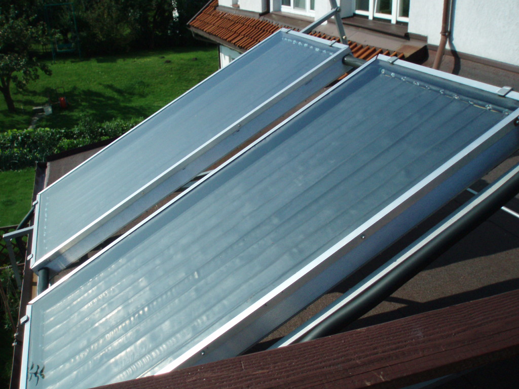
The absorber consists of 11 pipes of internal diameter of 8mm and cumulative buses 22mm. The piper are soldered to the cumulative buses by hard solder (brass). Copper plate which was previously bound (to reach a bigger surface of plate-pipe connection), is soldered the entire length by soft solder to those 11 pipes. Absorber was blackened.
Ready absorber was put in the housing made of 10cm wide grooved channel section. A galvanized metal sheet, riveted from three sides to the channel section, screwed from one side, was placed on the bottom. Under the plate and on the corners of the housing, there was silicone resistant to high temperature up to 350 degrees Celsius. The inside of the housing was isolated by 10cm thick mineral wool.
The whole was covered with 4mm hardened glass, under which there was also silicone resistant to high temperature. That in the case of one collector was disappointment, because the silicone smelled strongly like vinegar and reacted with blackened surface, which in places turned green. So it is better to choose silicones which smell less.
Another layer of silicone was put on the glass and then aluminum angle , also screwed to the channel section on the side.
The installation is made of copper pipes 15mm, covered with caoutchouc insulation and insulated with caoutchouc band on the connections.
The rack of collectors was made of 30x40mm steel profiles.
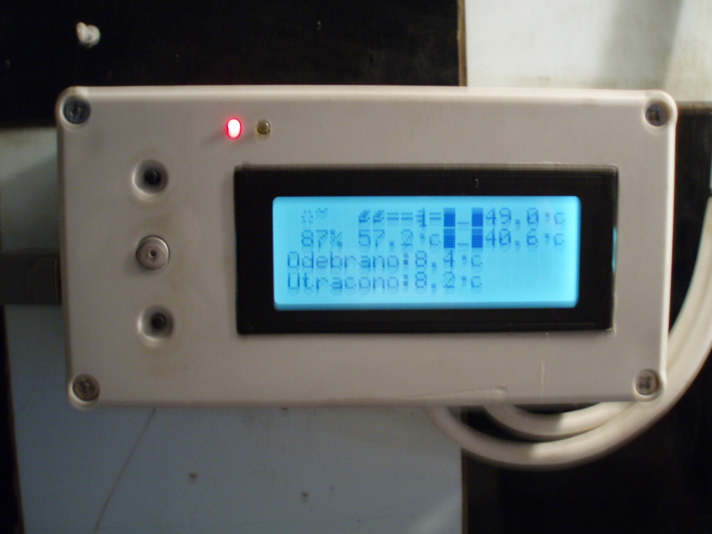
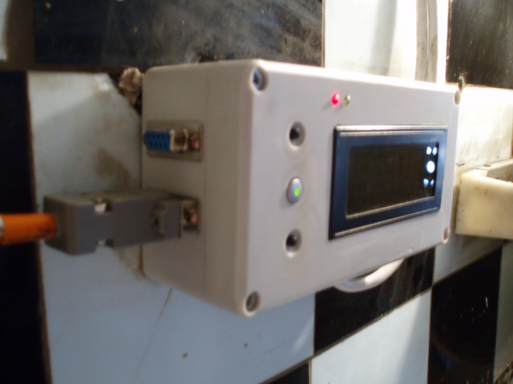
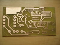
The driver mas made on Atmega32 system. Soft is still being changed. The system has 3 DS18B20 sensors.
Features of the driver:
- set the temperature of turning the pump (temperature difference between the collectors and the tray input/output)
- set the temperature of turning off the pump (---||---)
- set the switching threshold of the alarm
- save to the EEPROM
- set the short-circuit current on the line that powers sensors, current measuring
- set the reference temperature (or tray output or input temperature)
- measurement of sunlight
- daily recorder (max. sunlight, max. collectors temperature, etc.)
- set the time after which LCD backlight turns off
- set the minimum sunlight at which the solar collectors heat (eg needed when the alarm sounds caused by the lack of a sensor, then depending on the sunlight, the pump turns on or not. This allows the collectors wouldn't cool water which was already heated up)
COM connectors which are visible next to the driver are used to: upper one to program, lower one to plug the sensors.
In a sunny day the temperature of water would rise from 20 to 40 degrees Celsius or if it was 40, up to 55 degrees Celsius. Tank capacity is 250l. The collectors should be placed on southern side to reach the best performance possible.


Link to original thread – Kolektory słoneczne + sterownik