Continue to Site

Welcome to EDAboard.com

Welcome to our site! EDAboard.com is an international Electronics Discussion Forum focused on EDA software, circuits, schematics, books, theory, papers, asic, pld, 8051, DSP, Network, RF, Analog Design, PCB, Service Manuals... and a whole lot more! To participate you need to register. Registration is free. Click here to register now.

SNR calculation using cadence Spectre

Status
Not open for further replies.

kapil411

Newbie level 5
Newbie level 5
Joined
Aug 11, 2007
Messages
9
Helped
0
Reputation
0
Reaction score
0
Trophy points
1,281
Activity points
1,355
hiiiiiiii

I'm working on sigma Delta ADC
CAN ANY1 PLEASE HELP ME ON WORKING WITH CADENCE SPECTRE FOR snr CALCULATION

TRANSIENT ANALYSIS DON E WITH
FIN=50HZ (OSR=64) (SINE WAVE)
FS=12800HZ=CLK FREQUENCY

HOW MANY CYCLES I SHOULD RUN THIS TRANSIENT ANALYSIS??

wats d funda of skipstart,skipstop, strobeperiod
& HOW TO CHOOSE

STROBEPERIOD?
SKIPSTART?
SKIPSTOP?
IN ORDER TO CALCULATE snr
PLEASE HELP ME IN FIGURING OUT THESE VALUES...
 

RTFM! See your Spectre® Circuit Simulator Reference or Virtuoso© SpectreRF Simulation Option User Guide !
 

ya thanks,a lot but

but regarding....
how to fix

no of samples?????????

how to fix time period to be used for calculation of FFT SNR??????
 

hi thank u
many thanks for your reply,

ya i got intial basic calculatiomns
_________________________________________________-
my design calculation r

input sinusoidal freq=50hz suppose

clk freq =12800

no.of samples =8192

so (50/12800)*8192=32
(ending upto nearest prime number= 31 0r 37)

so my calculated i/p freq

12800*31/8192= 48.4375 hz

so,its my adc input freq

taking fft 0f 8192 points for 31 i/p sinusoidal clock cycles

leaving starting 10 clockcycles for settling transient signal i'm doin

so i'm trying to find fft of window from

0.206451612 to next 31 cycles.... presently simulating using cadence spectre...


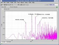
Do my fft spectrum shows up noise shaping????

am i missing any steps?????

what additional steps shud i follow for better SNR & resolution ????

once again thanks for ur patience & vital information

thank U :)
+++++++++++++++++++++++++++++++++++++++++++++++++++++++

for further information download the attachment
its a maxim company paper

thanks & all d best

with regards,
mnk
 

Attachments

  • AN1819.pdf
    71.7 KB · Views: 227
Last edited:

Do my fft spectrum shows up noise shaping????
Due to oversampling, yes. But this also depends on the structure of your ΔΣ .

am i missing any steps?????
No, I think your coherent sampling calculation is ok.

what additional steps shud i follow for better SNR & resolution ????
More samples, of course, if you can spend the time or cpu (farm) power. Perhaps already 16384 samples would show better results. Sheldon - in his Reply #1 suggested even 2^18 samples! 262144 samples, not 266144 , of course ;-)
 

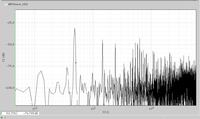
helllllllllo plz hav a look at cadence psd plot of SD modulator


what could be possible reason for spikes at other frequencies?????

I also could nt see perfect noise shaping??????

please help in figuring out the solution
 

My guess is that the modulator is resetting or saturating. Check the voltage at the output of each integrator.
 

thanks for ur reply....

ya i checked tht voltage at integrators....

according to me,......i thought my input amplitude might be causing the problem....
my design spec...


power supply of 1.2v
intially applied 1.8V(p-p)
thought it might be causing problems...


then after so i decreased my input amplitude..0.6vp-p
got much painful results...psd with harmonics.....


can any 1 please do help regarding this....

this would also be helpful to others.....
please any1 help me

thanking you in advance...
 

Without any more information on the actual design, it would be guesswork. At any rate, start with an input voltage of 100mVp-p and check the loop.
 

Status
Not open for further replies.

Similar threads

Part and Inventory Search

Welcome to EDABoard.com

Sponsor

Back
Top