Continue to Site

Welcome to EDAboard.com

Welcome to our site! EDAboard.com is an international Electronics Discussion Forum focused on EDA software, circuits, schematics, books, theory, papers, asic, pld, 8051, DSP, Network, RF, Analog Design, PCB, Service Manuals... and a whole lot more! To participate you need to register. Registration is free. Click here to register now.

Sinewave inverter prototype...

Status
Not open for further replies.
first test of stm8 DC_DC 12_320 converter
 

Attachments

  • stm8 DCDC c&hex&pcb.zip
    28.7 KB · Views: 207

@DeepOne you seems to be in Love with STM, I wonder it could have been done with SG3525 with better feedback control and cost. alternately DC 2 DC stage can be done with ATmega8 and the dip version can easily be soldered compared with smd.
I think one 2304 is enough for push-pull design with using the upper charge pump driver too for low side driving.
 
Last edited:

I see STM8 is reliable mcu in hindranced environment, it has 16MHz internal RC (Mega8 only 8MHz, external crystal reduces reliability) and more developed abilities to PWM generations. Additionally STM8S (1,25 USD beside me) cheaply than ATMega8A and, if required, migration to cheap STM32 is not hard.
DC 2 DC stage can be done with ATmega8
yes, of course - this possible do even on ATtiny13.
it could have been done with SG3525
yes, but using mcu somewhat simplifies problem in part of checking batteries voltage, soft starting and other auxiliary functions.
dip version can easily be soldered compared with smd.
in my sight smd version is more easy and quickly soldered ))

- - - Updated - - -

test with 100W incandescent lamp ok, with removed capacitor from HV measuring part (it cause voltage fluctuations).
 
Last edited:

OK, what are using for sinewave generation after this stage (DC2DC)
 

Would you plz modify the schem in message #218 or #220 for STM8S003F3 because its the only chip available here, and don,t have the tools to modify the code or option bit as I have to program the chip using an Universal programmer.
I will use 2sa1383 2sa0683 for the complementary pair after 6n137.
 
Last edited:

STM8S003F3 as i know exists only in 20pin TSSOP(or QFN) package so remapping options bits must be programming. But this bits also may be programmed by mcu itself. Well i shall try this.
 

version with option bits self progrraming
 

Attachments

  • 8s103f3_self_opt_prog.zip
    74.5 KB · Views: 262

Ok DeepOne, Can you help me design the DC-AC side of this and i pay for it
 

I want the stm type with ir2110 and multiple mosfets to handle 4kva. i want you to construct it and i will pay for it. we do not have this chip in nigeria talk more of the programmer

- - - Updated - - -

IMG_20141023_133530.jpg 
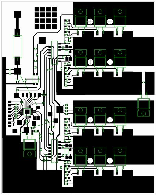
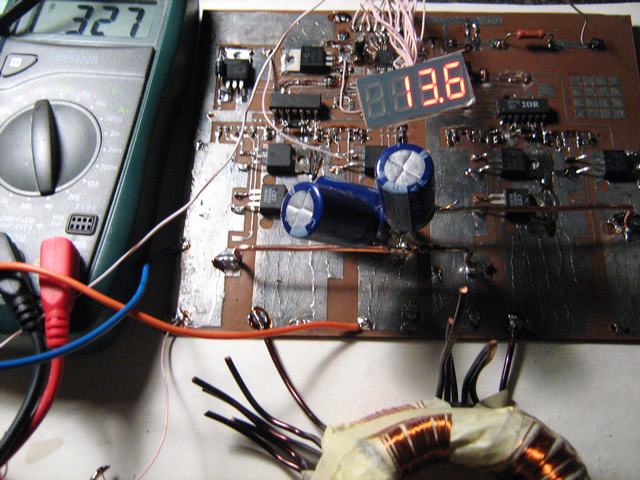
my dc to dc converter driver and transformer section
 

I'm not professional and do this only for fun and when i have free time and suitable mood.
Also i think 6N137 optocouplers or HCPL drivers in such application is significally more reliable decision than IR211* chips.
 

at first sight on such DC_AC converter it's scheme could look as that
 

@DeepOne,
But,
if optocoupler is used to drive high side transistor, is not there require independent supply (ground cannot be the same of the main supply and the high side driver supply) to drive?
 

For optocoupler feeding possible use same scheme as with IR2110.
 

ok i get you, a quick one, do you have a circuit for 50% duty cycle of uc3843
 

about 3843 circuits i know not more than you )

- - - Updated - - -

seems hardware deadtime generation is uncomplicated task even for attiny13 )
 

Attachments

  • c&hex&proteus.zip
    15.3 KB · Views: 170

more complicated tiny13 circuit
 

Attachments

  • t13_fb_dtg_c&hex&proteus.zip
    95.4 KB · Views: 238

Status
Not open for further replies.

Part and Inventory Search

Welcome to EDABoard.com

Sponsor

Back
Top