Continue to Site

Welcome to EDAboard.com

Welcome to our site! EDAboard.com is an international Electronics Discussion Forum focused on EDA software, circuits, schematics, books, theory, papers, asic, pld, 8051, DSP, Network, RF, Analog Design, PCB, Service Manuals... and a whole lot more! To participate you need to register. Registration is free. Click here to register now.

Simulating 433Mhz Dipolo with ADS

Status
Not open for further replies.

tomars

Junior Member level 2
Joined
May 25, 2022
Messages
23
Helped
1
Reputation
2
Reaction score
0
Trophy points
1
Activity points
128
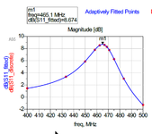
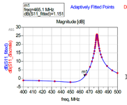
I need help for this.

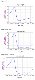
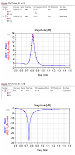
I made two simulation, using one pin and grond, and one +pin and one - pin
Result is more different.
What is the right method ?
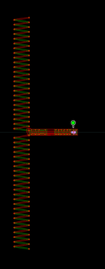
Using one pole and Grond, i see little activity on bottom pole, on momentum Visualization, animation.

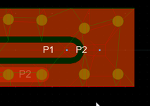
P1 P2 are +/- pole
sim2 is P1 + GND
sim2_2 is P1+ P2-
 

Attachments

  • Pin.png
    Pin.png
    34.9 KB · Views: 154
  • sim2.pdf.png
    sim2.pdf.png
    42.2 KB · Views: 167
  • sim2_2.pdf.png
    sim2_2.pdf.png
    43.5 KB · Views: 168
  • Dipolo.png
    Dipolo.png
    44 KB · Views: 164

Maybe I understood.
But I don't understand the program.
Can you help me to found error ?
 

Attachments

  • Sim2.zip
    19.6 MB · Views: 155
Last edited:

First project is from gerber.
I made new one, step by step, from youtube tutorial.
But some result is positive.

dB(S(1,1)) is dB(S11) and it is antenna gain ?
Same to 8DBI attached ?

d1.png
 

    FvM

    Points: 2
    Helpful Answer Positive Rating
S(1,1) is NOT Antenna Gain. It's just related to Input Impedance. In order to obtain Antenna Gain you have to simulate your antenna within 3D simulator and obtain Radiation Patterns( for different angles and Horizontal-Vertical both) . HFSS is an appropriate tool for this purpose. Sonnet and ADS Momentum can also be used.
You will find- if you do a set-up correctly- an Antenna Gain compare to Omnidirectional Antenna.
 

I only need to be tune antenna.
It is not important to know gain.

Can please donload my project for check where is error ?
It is right, use Pin & GND, or Pin+ & Pin- for checkh dipole ?
 

This test for 1Ghz 1/4wave and dipole.
For understand ADS, that I do not understand
 

Attachments

  • dp1.png
    dp1.png
    79.5 KB · Views: 148
  • dp2.png
    dp2.png
    86.1 KB · Views: 147

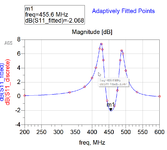
This seeems right ?
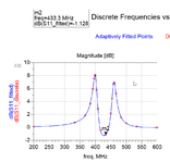
-2 at 455MHZ ?
And how to show impedance on OHM ?
 

Attachments

  • d3.png
    d3.png
    43 KB · Views: 144

Can please you help me to found problem ?
I do not know how to do.
--- Updated ---

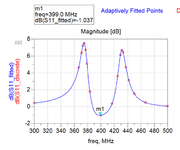
Adding 4 SPires The Frequency Has Come Down
Too now.
But I don't understand why you all say that the graph is wrong.
I don't know nuthing of S and DB, only i need PCB 433Mhz antenna.
 

Attachments

  • d4.png
    d4.png
    57 KB · Views: 141
Last edited:

Create an Archive file from your project. Don't zip the whole directory, just create related archive file and post it here.
 

Thank you

If you mean WorkSpace Archive Command.
I compressed the file 5.7zads on 5.zip

This today monopole from gerber.
--- Updated ---

And this result
 

Attachments

  • 5.zip
    24.5 KB · Views: 149
  • d5.png
    d5.png
    26 KB · Views: 146
Last edited:

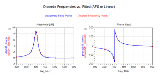
Ignore monopole.
This dipole, seems right for 433Mhz
 

Attachments

  • 6.zip
    2 MB · Views: 148
  • d6.png
    d6.png
    35.5 KB · Views: 133

There are many mistakes..
-Merge all objects which are on the same layer and simplify the layout.
-You drove P1 on BOT layer but the GND was Implicit. It must be TOP layer. See Port dialog in project file.
-Tan Delta of FR4 is low, increase to 0.04.
-This antenna does not work @ 433 MHz, Impedance is best @381MHz
Impedance.png

Current.png

Antenna.png
 

Attachments

  • 6.rar
    3.3 MB · Views: 128
  • Like
Reactions: FvM

Very good. Out of curiosity, do you understand how the previous simulations achieved positive dB(S11)?
He had defined a Port on Bottom layer and GND Reference of this Port was Implicit Momentum GND Layer.
But There was also Top layer and this Port had to be referenced to Top Layer.
So, there will be a generator between Top and Bottom layer and the antenna will be correctly driven.
 

Thank You Very Much.

In front of the PCB I have a 5mm acrylic panel, and behind the concrete wall.
Could the program consider them?

Where do I find Delta setup?
 

-Merge all objects which are on the same layer and simplify the layout.
-You drove P1 on BOT layer but the GND was Implicit. It must be TOP layer. See Port dialog in project file.
-Tan Delta of FR4 is low, increase to 0.04.
-This antenna does not work @ 433 MHz, Impedance is best @381MHz
I am trying to replicate your work, and finally, only now, I get 381MHz

-Merge all objects which are on the same layer and simplify the layout.
Handmade editing ?
Removing trash orphan track ?

-Tan Delta of FR4 is low, increase to 0.04.
I can't find this parameter in any ADS setup

How can I add 5mm acrylic on one side and wall on the other side ?
 

-Tan Delta of FR4 is low, increase to 0.04.
I can't find this parameter in any ADS setup

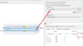
You need to open the EM substrate in the substrate editor, then select the FR4 layer, then change material definition.

To add acrylic and wall (concrete?) material you need to add these materials as layers in the EM substrate.

Getting proper results from EM simulation requires a skilled user. If you are new to ADS and have no time to attend the Momentum training, have a look at the tutorial videos by Anurag Bhargava:
--- Updated ---

How can I add 5mm acrylic on one side and wall on the other side ?

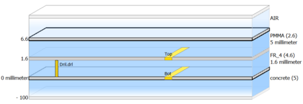
Not sure if I understand your setup, but I changed your substrate to 5mm acrylic (PMMA) on one side and an infinite layer of concrete on the other side.

Resonance is shifted down to ~230 MHz then, the modified ADS model is attached. To move resonance back to 433 MHz, reduce dipole length. Try 53% of the original size.

Good luck!
Volker
 

Attachments

  • ads_substrate_editor.png
    ads_substrate_editor.png
    135.9 KB · Views: 153
  • substrate_pmma.png
    substrate_pmma.png
    14 KB · Views: 132
  • dipole_pmma_concrete.zip
    1.6 MB · Views: 135
Last edited:
thank you

About graph.
I have:
-3.5 for air db(S11)
-4.5 for acrilyc
-20 for acrilic + concrete

What does it mean ?
How do I real the impedance in Ohm and the Ros ?

Where can I find better delta parameters for cement (concrete) and acrylic at 433MHz ?
 

Status
Not open for further replies.

Part and Inventory Search

Welcome to EDABoard.com

Sponsor

Back
Top