Continue to Site

Welcome to EDAboard.com

Welcome to our site! EDAboard.com is an international Electronics Discussion Forum focused on EDA software, circuits, schematics, books, theory, papers, asic, pld, 8051, DSP, Network, RF, Analog Design, PCB, Service Manuals... and a whole lot more! To participate you need to register. Registration is free. Click here to register now.

[SOLVED] Simple transistor based power supply for stepper motor doesn't work

Status
Not open for further replies.

elPresidente

Junior Member level 2
Joined
Jul 27, 2012
Messages
20
Helped
0
Reputation
0
Reaction score
0
Trophy points
1,281
Activity points
1,476
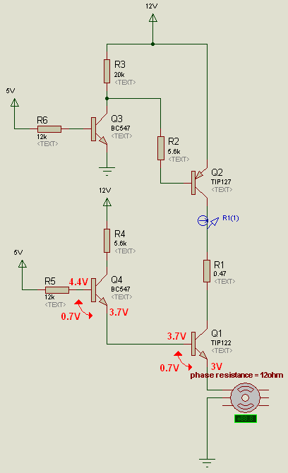
Hallo, I'm trying to make switching power supply to my stepper motor. Thought that this circuit will be good but it doesn't work properly - I mean as i think it should work - transistors got some kind of oscillations and load (stepper motor) current is only about 0.25 A and i would expect it to be equal to ohm law I = U/R = 0.96 A.
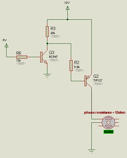
When Stepper motor phase is connected after 0.47 ohm resistor, between transistors it works fine but i have to do it in shown order.
Could anyone explain me why it doesn't work? Which property of transistors make it so?
93_1345761999.png
 

what happened with this circuit ?
did u check currents and voltages at various points at various conditions
 

what happened with this circuit ?
did u check currents and voltages at various points at various conditions

It's hard to explain with my poor english. So current through stepper motor phase isn't equal to (power supply voltage)/(serial resistance in circuit) which is because of transistor switching oscillations (open-> closed-> open...). I don't know the reason of this switching oscillations, i expect transistors to open when i put 5V uC signals on their gates. I was trying to put lower transistors' biasing resistors, the same behavior. I was trying to put bigger sense resistor (1k) between transistors as R1 and it works then, but i can't have 1k sensing resistor, i put stepper motor phase connected between transistors and it also works but it has to be below. I also tried to change powers supply from 12V to 18V and it's the same. Need some more explanations?
Don't understand WHY this circuit behave in such strange way and don't know what to to do to make it working.
 
Last edited:

This is the problem:


This should work better:
 

What are you trying to do with this circuit?
Is it just to power on/off the motor?

If so then why don't you use a simple transistor configuration which can be driven from your mcu since tip122 is a Darlington?
You just need to connect it at the ground side as a low side switch, emitter to gnd and collector to motor.

- - - Updated - - -

This is the problem:

Actuallt TIP122 is a darlington so you should expect a higher Vbe
 

I'm trying to create chopper based power level for four phase stepper motor. Resistor R1 = 0.47 is used as a current sensing resistor. I was trying with two complementary transistor circuit because of freewheeling currents. There was also freewheeling diode in my main circuit but i took it away to not complicate thing here. I wanted first TIP127 transistor to be closed when i close first phase and all others transistors in other phases also to be closed in the same time except of TIP122 for first phase to let freewheel current only through first diode and let me sense current in this phase. Look on the scheme below.
It would let me sense current during closing phase and and switch it on again when freewheeling current falls below given threshold.

Supply on the scheme means power supply voltage from 12V to 30V


Stepper Motor.png

@godfreyl
Thanks
Yes, this is better but not exactly what i expect, i mean sensing freewheeling currents properly, not divided by four phases.

Sorry for not telling "the whole truth" from the beginning.

@alexan_e
"If so then why don't you use a simple transistor configuration which can be driven from your mcu since tip122 is a Darlington?"
I thought that it would be kind of protection for uC in a case when darlington was damaged.
 
Last edited:

Actuallt TIP122 is a darlington so you should expect a higher Vbe
Oops.:oops:

I'm trying to create chopper based power level for four phase stepper motor. Resistor R1 = 0.47 is used as a current sensing resistor......

It would let me sense current during closing phase and and switch it on again when freewheeling current falls below given threshold.
I think it will be easier to sense the current flowing from common to ground, like this:

This will sense the freewheeling current, and also sense the current when one TIP127 is switched on.
 

I think it will be easier to sense the current flowing from common to ground, like this:
Yes, it would be good but unfortunately i want my driver to work in half-step mode where one and two phases are on in sequence. I could have not sensed two phases in the same time.

In the end i've done it almost like you but with sensing resistors in series with each phase.
 

Status
Not open for further replies.

Similar threads

Part and Inventory Search

Welcome to EDABoard.com

Sponsor

Back
Top