- Joined
- Jul 4, 2009
- Messages
- 16,273
- Helped
- 5,140
- Reputation
- 10,309
- Reaction score
- 5,131
- Trophy points
- 1,393
- Location
- Aberdyfi, West Wales, UK
- Activity points
- 137,729
Not quite right.
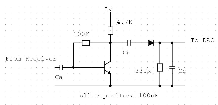
The transistor needs to be "biased", technically that means the correct base current has to flow in order that it isn't forced into a non-conducting state or a fully conducting state but somewhere between the two. In that middle state, a small amount of bias change will make a large change in collector current and amplification is achieved. What Cc does is allow the signal (the audio waveform) to change the bias and therefore be amplified but still isolates any steady voltage that is present on the radio output connection. For example, if the Cc wasn't there and the radio had an 8 Ohm loudspeaker between the output connection and ground, all the current through Rb would flow through the loudspeaker instead of the transistor and it would never conduct. Likewise, if the radio output had say 6v on it, the transistor would be forced so hard into conduction it could be damaged. The capacitor keeps the bias voltage and anything other than the signal separated.
The collector of the transistor will have a voltage on it because current flows through RL. As in the case of Cc, what we want to do is keep that voltage out of the DAC and only let the signal through so we use another capacitor to block the steady voltage. After that capacitor there should be an amplified version of the signal from the radio. The diode comes next, it's purpose is to rectify the signal because the DAC will not measure negative voltages and can be damaged easily if a negative voltage reaches its input pin. The diode 'blocks' the negative half of the signal while letting the positive parts of the cycles pass through. Don't get fixated on the 0.7V drop, that's the forward saturation voltage and isn't too important in this application. The positive cycles now need something to average them so the voltage from them rises according to how loud the audio is, another capacitor, after the diode and connected to ground works as a reservoir, it tops up from the incoming signal and holds the peak voltage it gets from the diode. The ADC can easily read this because it is the correct polarity and only changes slowly. Finally, the reservoir should have a resistor connected across it to allow some of the charge to leak away. A low value resistor will leak it faster and the voltage will more closely follow the signal, a larger ne will mak the change slower. You need a compromise value that allows a quick enough response to sound but doesn't make the ADc reading drop too low in short pauses or interference.
Brian.