Continue to Site

Welcome to EDAboard.com

Welcome to our site! EDAboard.com is an international Electronics Discussion Forum focused on EDA software, circuits, schematics, books, theory, papers, asic, pld, 8051, DSP, Network, RF, Analog Design, PCB, Service Manuals... and a whole lot more! To participate you need to register. Registration is free. Click here to register now.

Simple constant current source question

Status
Not open for further replies.

neddie

Full Member level 5
Joined
Feb 23, 2010
Messages
251
Helped
41
Reputation
82
Reaction score
35
Trophy points
1,308
Location
South Africa
Activity points
3,026
Attached is a LTSpice circuit of a simple constant current source. A standard pnp / zener arrangement.
I've used this circuit years ago , but I don't remember it being as good as the simulation
suggests. Set for about 1mA output , it only varies by 25uA with a temperature change from 20 to 80
degrees and a load change from 10 to 100 ohms.
Is spice lying to me :0) When I get home I'll build it and see , just wondering.
Cheers
Neddie
sorry , forgot attachment :0(
 

Attachments

  • simple constant current source.zip
    610 bytes · Views: 112
Last edited:

Hi,

usually the BJT pn tempco is about -2mV/K

the tempco of zeners with Vz < 5 = is negative, too
The tempco of zeners with VZ >5.5V is positive.

So if you use a zener with Vz = about 5.6V combined with a BJT as current source you get very low tempco.

Klaus
 

As the transistor's Vce is sufficient to maintain it way out of saturation, the simulated values are not that unreasonable.

Having said that, the late analog guru Bob Pease had as its professional mantra not to trust simulation 100%....a breadboard is always required to validate a circuit with real world components.

For instance, some lower grade carbon film resistors have significant Tempcos.....that would add additional errors.
 

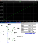
Below is a sim of the circuit with slight change in the zener voltage and the addition of a series diode to improve the temperature compensation. The original circuit had a 24.7uA change over the temperature range and the modified circuit has only a 1.2uA change.

Of course that doesn't account for any resistor temperature changes or other secondary effects. Any of those will show up in breadboard testing.

Constant Current.gif
 

I have to agree with Bob Pease (who am I to disagree :0) ) , breadboard testing is a must. I built the circuit last night. Worked surprisingly well , probably not far off the simulation. I did't have a high quality multimeter with me to accurately measure uA accurately though.
Will take a better meter home tonight and try and do some accurate measurements. I'll give your circuit a go as well Crutschow.
cheers
Neddie
 

Status
Not open for further replies.

Similar threads

Part and Inventory Search

Welcome to EDABoard.com

Sponsor

Back
Top