guitarnoob123
Junior Member level 1
Hello,
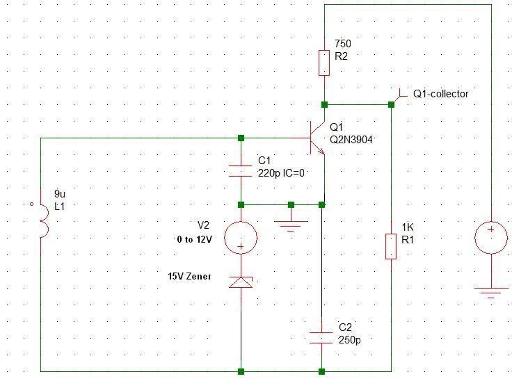
This particular circuit provides a good periodic waveform when I implemented it in the lab
However, I can't seem to make a transient analysis in simetrix. I wanted to add a few components and simulate before I test it again.
Any ideas? Is it because I didn't use any resistors for biasing? Take note that the BJT was biased properly in the lab (it works!).