Continue to Site

Welcome to EDAboard.com

Welcome to our site! EDAboard.com is an international Electronics Discussion Forum focused on EDA software, circuits, schematics, books, theory, papers, asic, pld, 8051, DSP, Network, RF, Analog Design, PCB, Service Manuals... and a whole lot more! To participate you need to register. Registration is free. Click here to register now.

Shifting register data to another register

Status
Not open for further replies.

JonathanRalph

Newbie level 6
Joined
Aug 27, 2016
Messages
14
Helped
0
Reputation
0
Reaction score
0
Trophy points
1
Activity points
131
Hello all,

Let's say I have two registers declared, namely register A and register B. Both can store 1 bit (binary) of data. If I have an input of 1, register A should store a value of 1. If I supplied an input of 1 again, the data that was recently stored to A should jump to B and the new input would be stored to A. It's like a first in first out scenario, but with whole registers being involved. I coded my program this way:
...
Code:
if (data_in==1)
begin
  B=A;
  A=1;
end
...

I thought that the program would perform the first line before reading the second line. The result I expected was for B=0 (since it is initially zero) and A=1. But after executing the code, both A and B became 1. Any suggestions? (I'm still new to verilog btw)
 
Last edited by a moderator:
Hi,

it seems to be correct, but it could be wrong, too.

It is not clear what you EXACTELY want.

****
some possible problems:
* we can´t see variable default values (maybe both are set to 1 at the beginning, then nothing ever will happen)
* With your program you NEVER set A=0. Therefore once A is set to 1 it will never become 0, once B is set to 1 it will never become 0, too.
* it is not clear how often or at which event you call your program. If this is wrong, then both A and B will immediately 1..

Klaus
 

Thanks for the reply klaus.

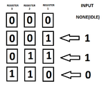
Actually, the result that I wanted is shown in the image below.
for_edaboard.png
The three boxes in the image are 7 segment displays, each with corresponding registers. I wanted that the data in each register would shift to the left each time a new input is given. However the code I previously gave resulted in this:
for_edaboard2.png
I only input a value of 1 only once but all three showed up like this. Did I accidentally perform a loop in my program?
 

Did I accidentally perform a loop in my program?

The use if the if should be avoided if all possible outputs are not covered.
Perhaps it is missing the else statement, otherwise compiler decides for you.
 

I was thinking of using a case statement to transfer each segment data one by one to avoid the risk of accidentally overwriting before data transfer.
Code:
case (count)
		4'b0000: seg5=seg4;
		4'b0001: seg4=seg3;
		4'b0010: seg3=seg2;
		4'b0011: seg2=seg1;
		4'b0100: seg1=seg0;
		4'b0101: seg0=in
		endcase

The counter here is used for sequencing. For each count, the case evaluates the value then executes its respective task. Then the counter increments by one and then executes the next task, and so on. All this is executed in one push of a button (when providing an input). But I still have difficulty implementing this logic into my codes.
 

I would recommend to deal with the previous approach, managing each incomming bit, one by one. With the above switch-case, you can also do not cover all possible combinations, in the case of something going not as expected.
 
Thanks. I'll come back here again after doing some recoding. I'm still open to suggestions :)
 

Verilog has two assigns blocking (=) and non-blocking (<=). To correctly describe (not program) a shift register (actually all flip-flops) non-blocking assignments should be used.

You also do not show the rest of you code so you may be using alway incorrectly and could be declaring things incorrectly.

The proper way to describe a shift register is as follows:

Code Verilog - [expand]
1
2
3
4
5
6
reg  a =1'b0;
reg  b =1'b0;
always @(posedge clk) begin
  a <= 1'b1;
  b <= a;
end


- - - Updated - - -

BTW, Verilog is not programming it is a hardware description language, so loops are not the same as temporal loops in programming languages, loops instead are unrolled to create copies of hardware elements.
 
Last edited:
Hi,

I´m not sure what this actually means:
I wanted that the data in each register would shift to the left each time a new input is given.

Now I don´t see HOW it is detected that a new input is given.
--> The OP has to define this.

All the codes above don´t wait for anything.
They just shift the input with every system clock.
Imagine the system clock is 1MHz, then it takes 1 us to shift the 1 into A, and another 1us to shift A to B.
For sure the eye can´t see the 2us delay.

We can not know if there are two keys: "1" and "0"

When the clock is 1Hz, then one can see the shift.

Klaus
 

All the codes above don´t wait for anything.
They just shift the input with every system clock.

That is why ads-ee mentioned the importance of the sensitivity list, which could imply on differences on implementation.
Once OP did not mention it on the first code, the circuit description as a whole is not complete.
 

sorry about that. here is the code I managed to build as of now

Code Verilog - [expand]
1
2
3
4
5
6
7
8
9
10
11
12
13
14
15
16
17
18
19
20
21
22
23
24
25
26
27
28
29
30
31
32
33
34
35
36
37
38
39
40
41
42
43
44
45
46
47
48
49
50
51
52
53
54
55
56
57
58
59
60
module Pattern(clock,
 one,
 zero,
 reset,
 bcd0,
 bcd1,
 bcd2,
 bcd3,
 bcd4,
 bcd5);
 
// inputs
input clock;
input one;
input zero;
input reset;
 
// outputs
output [6:0] bcd0;
output [6:0] bcd1;
output [6:0] bcd2;
output [6:0] bcd3;
output [6:0] bcd4;
output [6:0] bcd5;
 
 
// registers
reg seg0;
reg seg1;
reg seg2;
reg seg3;
reg seg4;
reg seg5;
reg in;
 
// input to register "in"
always @(posedge clock or negedge reset)
begin
    if (!reset or !zero)
    begin
        in=0;
    end
    else if (!one)
    begin   
        in=1;
    end
end


// 7 segments, cases are on another file        
SevenSegment a(seg0, bcd0);
SevenSegment b(seg1, bcd1);
SevenSegment c(seg2, bcd2);
SevenSegment d(seg3, bcd3);
SevenSegment e(seg4, bcd4);
SevenSegment f(seg5, bcd5);
 
 
endmodule


Hi,

please be more descriptive.
It is rather difficult for us to go through foreign code to find out what the writer wants to achieve.

Now I see two inputs: "one" and "zero". Are these input keys you want to react to?

If so, then first you need to ensure that they are debounced.
Next is that you need to find out the signal EDGE when the key is pressed.

For this you need to compare the state of the key one clock tick before. If it WAS unpressed, and NOW it is pressed then you found the EDGE.
This EDGE is the clock enable for the shift function.

***
In short: The shift function must not be triggered on every clock (edge) but on every key_press_edge.

***

Imagine a 1MHz clock.
And a key that is not pressed for half a second and then pressed for half a second.

--> 500,000 clock ticks key_not_pressed (not of interest)
--> exactely 1 clock tick where the key press EDGE is active (interesting!!!)
--> 500,000 clock ticks key_pressed (not of interest)

Klaus
 
Use Verilog 2001 module port syntax, you are using the original '87 syntax (which redundantly calls out the port names twice).

Code Verilog - [expand]
1
2
3
4
5
6
7
8
9
10
11
12
module Pattern (
  input     clock,
  input     one,
  input     zero,
  input     reset,
  output    bcd0, // aren't this supposed to be multibit wide buses?
  output [3:0]   bcd1, // i.e. like this, assuming this is a binary coded decimal digit value?
  output    bcd2,
  output    bcd3,
  output    bcd4,
  output    bcd5
);


Don't use the reset logic as a LOGIC input, this is bad design.

Code Verilog - [expand]
1
2
3
4
5
6
7
8
9
10
11
12
// input to register "in"
always @(posedge clock or negedge reset)
begin
    if (!reset or !zero)
    begin
        in=0;
    end
    else if (!one)
    begin   
        in=1;
    end
end


You currently have this as priority encoded to generate a 0 on in on an active low zero. I would make the name indicate the active polarity being low as opposed to the normally active high signals, e.g. zero_b or zero_n (_b for bubble, _n for negative). You are also still incorrectly using = blocking assignments where you should be using <= non-blocking assignments. Always use non-blocking assignments to infer flip-flops this avoids the simulation vs synthesis mismatches that can occur.

Properly coded asynchronous reset using non-blocking assignments...

Code Verilog - [expand]
1
2
3
4
5
6
7
8
9
10
11
12
13
14
15
16
17
18
always @(posedge clock, negedge reset) begin
    if (!reset) begin
      in <= 1'b0;
    end else if (!zero && one) begin    // only zero is active
      in <= 1'b0;
    end else if (zero && !one) begin    // only one is active
      in <= 1'b1;
    end else if (!zero && !one) begin   // opps both zero & one are active
      // explicitly hold last value
      in <= in;
      // set to zero
      in <= 1'b0;
      // make it X so you know your simulation has a fault
      in <= 1'bx;
      // or leave this branch out entirely and let the last
      // value be held indefinitely.
    end
  end


Don't use positional association in your port mappings of instantiated modules:

Code Verilog - [expand]
1
SevenSegment a(seg0, bcd0);


Instead use named association port mapping:

Code Verilog - [expand]
1
2
3
4
5
6
7
8
SevenSegment a(.portname1(seg0), .portname2(bcd0));
// for a large number of port assignments the above code becomes impossible to read,
// so get in the habit of writing them with nice formatting on individual lines in nice readable
// columns.
SevenSegment a (
  .portname1    (seg0),
  .portname2    (bcd0)
);


And as KlausST pointed out debounce the inputs zero and one, and synchronize the release of the reset to the clock edge. It is okay to have an asynchronous reset but you should always ensure the release is synchronous to the clock edge, by running the release of the reset through a shift register chain.

Code Verilog - [expand]
1
2
3
4
5
reg  [3:0]   reset_chain;
  always @(posedge clock, negedge reset) begin
     if (!reset)  reset_chain <= 'b0;
     else         reset_chain <= {reset_chain[2:0], 1'b1};  // clean concise way to write a shift register
  end


This will still asynchronously assert reset but the release will be synchronous to the clock edges, this will ensure you don't violate the recovery/removal time of the FFs in a design.

- - - Updated - - -

I thought that the program would perform the first line before reading the second line. The result I expected was for B=0 (since it is initially zero) and A=1. But after executing the code, both A and B became 1. Any suggestions? (I'm still new to verilog btw)
I don't get why schools teach Verilog as a programming language. It should be taught after the first lessons on digital logic gates and logic functions like multiplexers, decoders, compares, etc. Once the student understands there is hardware and wires and stuff on a board then introduce Verilog/VHDL as a method to describe the same thing in a textual format rather than in schematics so we can synthesize those same type of circuits in an FPGA or ASIC. Maybe then students would not see Verilog as a programming language and insist on apply programming concepts to design hardware. It also makes me think hardware engineering is a dying discipline as most recent grads seem to be very weak in designing hardware, but are great programmers. In interviews I get blank looks when asking about metastability, impedance matching, clock jitter, etc.
 
Hi,

I don't get why schools teach Verilog as a programming language. It should be taught after the first lessons on digital logic gates and logic functions like multiplexers, decoders, compares, etc. Once the student understands there is hardware and wires and stuff on a board then introduce Verilog/VHDL as a method to describe the same thing in a textual format rather than in schematics so we can synthesize those same type of circuits in an FPGA or ASIC. Maybe then students would not see Verilog as a programming language and insist on apply programming concepts to design hardware. It also makes me think hardware engineering is a dying discipline as most recent grads seem to be very weak in designing hardware, but are great programmers. In interviews I get blank looks when asking about metastability, impedance matching, clock jitter, etc.

very true...sadly

Klaus
 

The use if the if should be avoided if all possible outputs are not covered.
Perhaps it is missing the else statement, otherwise compiler decides for you.

In Verilog this is only true in a combinational always block, if all possible combinations of the if cases are not covered the default is to hold the last updated value, this is why you have to be very very careful you do cover all cases in a combinational always block otherwise there is an inferred latch created as you must save the previous value.

For an edge triggered always block describing a FF the lack of an else or incomplete coverage of all if cases just defaults to holding the previous value.

- - - Updated - - -

Thanks. I'll come back here again after doing some recoding. I'm still open to suggestions :)

On this query for suggestions....

Draw a schematic of the circuit you want to design, then describe that schematic in Verilog. That is the best way to learn how to properly use Verilog or any HDL (Hardware Description Language). Reserve the Verilog "programming" to your testbench designs and BFMs (Bus Functional Models). And in these testbenches be careful and make sure your inputs to you DUT (Design Under Test) are not coincident with the clock edges or you might end up coming back with the problems described in this thread.
 

We were taught logic gates and functions, but I think our teacher wasn't that enthusiastic to teach us further into verilog principles. We were left there to code without guidance. Kinda sad though...
 

Thanks for the corrections. These were really helpful and I will gladly consider them in future projects.
For now, I'm just gonna go back and revamp my codes. Hopefully I can fix them in time.

Best Regards,
Jonathan
 

We were taught logic gates and functions, but I think our teacher wasn't that enthusiastic to teach us further into verilog principles. We were left there to code without guidance. Kinda sad though...
Wow, that seems to indicate you are going to a school that is not very good or at least hires less than competent instructors (that probably means the same thing).

From my personal experience there are few good sources of Verilog coding guidelines and information posted on the internet. Most of them all preach antiquated coding and really bad formatting. Only firms that specialize in training seem to have somewhat decent code samples on their websites. Forget about Opencores, most of the code examples from there are really bad, of course most of those samples are done by students much like yourself that learned from the plethora of bad coding examples strewn all over the internet. Very sad to say the least. Almost makes me want to start a coding guidelines blog.

- - - Updated - - -

Thanks for the corrections. These were really helpful and I will gladly consider them in future projects.
For now, I'm just gonna go back and revamp my codes. Hopefully I can fix them in time.

Best Regards,
Jonathan

The problem I see is your code (at least what you have posted) does not seem to do anything, or at least the function is not apparent based on your code samples (perhaps your samples were incomplete?). Your code in post #11 doesn't look like it will even do what you expect namely output a shifting number sequence on a set of five 7segment displays.
 

Status
Not open for further replies.

Part and Inventory Search

Welcome to EDABoard.com

Sponsor

Back
Top