Continue to Site

Welcome to EDAboard.com

Welcome to our site! EDAboard.com is an international Electronics Discussion Forum focused on EDA software, circuits, schematics, books, theory, papers, asic, pld, 8051, DSP, Network, RF, Analog Design, PCB, Service Manuals... and a whole lot more! To participate you need to register. Registration is free. Click here to register now.

Series connected Lead Acid Battery question

Status
Not open for further replies.

biswajitdas49

Member level 3
Joined
May 17, 2012
Messages
55
Helped
0
Reputation
0
Reaction score
0
Trophy points
1,286
Location
WEST BENGAL,INDIA
Activity points
1,726
HELLO EVERYBODY!!!
I have a four 12v series connected battery. Now I want to make a circuit which is cutoff charger connection when it reach it's set voltage that means upper limit and also cutoff battery output when it reaches it's low voltage value. Now I have a question ,

Can I make this circuit using op amp,if possible then it will be reliable for this purpose?
Because this battery is connected in series,so does I need to calculate the total voltage of the battery for this circuit or simply if I make this circuit for a single battery that means 12v reference, then all four battery is included in it?
What is the best and safe voltage for charging cutoff voltage and discharging cutoff voltage and how to calculate this?

please help me,I am novice in battery charging/discharging field.

thanks!!!
 

Unless you can maintain the specific gravity in each cell to be matched, then , safest is to match the voltage in each battery but shunt regulation in each battery to bypass over-voltage and detect under-voltage then if any is under, these are logically OR'd and a regulator for each battery is needed, as well as total pack regulation.

Otherwise, simple charger depends on chemistry, SLA vs flooded open cell, the SLA needs temperature correction. Also Ah capacity often limits max constant current (CC) charge rate for long life, where CC to 14.2V per battery then CV then reduce o float voltage when done.
 
you can use two op amps (one set for the charge voltage, one the discharge). I would use two relays, one to disconnect the charger and other the load, each with suitable rated contacts. I would be tempted to run the op amps of the charger supply - no point in discharging the batteries.
There are many ways of charging lead acids, but a rough and ready way is to charge them up to 14.6 and remove the load at 10.5V. The problem arises when you connect a 14.6 battery charger to a 10.5V battery, the current will be enormous and should be limited to C/10 (C = ampere hour rating of battery). The next problem is when the output voltage rises, the load relay will pull in, and the load will then draw current, so the charger should now supply Iload+C/10 Amps. So its best if the load relay does not pull in until the output is 14.6 V i.e. battery is fully charged.
For battery supported kit the " normal" PSU runs the kit and the battery plus charger is a standalone unit.
Frank
 
Thanks for reply,
Sorry guys actually I want such a indication circuit, when it reaches the set reference voltage value, which indicate by turn on a LED that shows the full charge, also cutoff the battery connection from charger, again cutoff the load when it reaches the reference voltage at discharging process. Now I have four series connected 12v battery that means 48v in total. My question was should I make this circuit by tapping a single 12v battery to show the indication for whole 48v or whole 48v I need to be measure to show the indication. In a single word, I want over-voltage and under-voltage indicator for (12volt * 4 series connected) battries with cutoff facilities.
 

My question was should I make this circuit by tapping a single 12v battery to show the indication for whole 48v or whole 48v I need to be measure to show the indication.

The batteries would need to perform identically, if you were to measure just one of them. Better to take an overall reading, then divide it down before you apply it to an op amp or comparator.

Notice that although the nominal system level adds up to 48 V, it can go as high as 60V or more when charging. This is too high for most op amps or comparators. You must regulate its supply V to a tolerable level. I used zener regulation when I constructed a charge controller for my 24V system.
 

Notice that although the nominal system level adds up to 48 V, it can go as high as 60V or more when charging. This is too high for most op amps or comparators. You must regulate its supply V to a tolerable level. I used zener regulation when I constructed a charge controller for my 24V system.

That means I have to scale it down.Can you provide me the voltage scaling circuit.how to calculate the wattage of the voltage divider resistor?
 

That means I have to scale it down.Can you provide me the voltage scaling circuit.how to calculate the wattage of the voltage divider resistor?

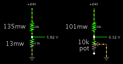
Here are resistive dividers, showing power dissipated.

2424315900_1415212833.png


Your measuring device will have its own internal resistance. It will draw a certain amount of current.

You must make sure this amount of current is very small, so that it does not load your voltage divider network.

That is the reason I chose values in the kOhm or tens of kOhm range. Because a typical meter, op amp, comparator, etc., is in the 1 M ohm range.

Thanks for reply.
Actually I have two questions-
1.Is your circuit is safe for LM358 op-amp ?
2.What would be the safest voltage I need to be chose for over and under voltage in a lead acid battery,please suggest me.
 

Thanks for reply.
Actually I have two questions-
1.Is your circuit is safe for LM358 op-amp ?
2.What would be the safest voltage I need to be chose for over and under voltage in a lead acid battery,please suggest me.

Absolute max is in specs!

–0.3 to 32V

Max common mode linear input is Vcc-2V to -0.2V

Charger without battery connection might be worst case.

-typically charge is 14-14.2V for open lead acid automotive Types. 14.8 might be a safe protection level per battery to prevent rapid hydrogen generation. Choose 14.2per for regulation limit.

If you don't balance the cells , how can you tell?
 

1.Is your circuit is safe for LM358 op-amp ?

The LM358 datasheet states +30V as the maximum rated supply V (single supply V).

A reasonable supply V for you to use would be 20V.

Voltage at the inputs must not go outside the supply rails. Therefore my voltage divider will provide safe values.

2.What would be the safest voltage I need to be chose for over and under voltage in a lead acid battery,please suggest me.

A charged 12V battery at rest reads 12.8 V.

10.5V is about the point where it is considered discharged. Somewhere between those points is where you'll set undervoltage.

A tapered charge typically reaches 14.4 V. That is a reasonable overvoltage setpoint.
 

Sorry for my late reply, somebody please tell me how to set the fixed reference voltage with the inverting terminal(-) of an op-amp for over-voltage protection.I want to scale min voltage=50v and max voltage=64v and Reference voltage would be vary from 0v to 5v.That means when a 12v series connected(12v*4=48v) discharged battery charging voltage reached at 64v, voltage divider would become 5v and give it to non inverting terminal(+) of an opamp and it's output becomes high.
after all I want to know how to set a fixed voltage reference with an op amp?
over voltage.jpg

thanks a lot for your opinion !!!
 
Last edited:

how to set a fixed voltage reference with an op amp?

You will apply a stable volt level to the other input. It can be almost any value somewhere between the 0 and 5V rails.

It must be adjustable. A potentiometer across the 0 and 5V rails can do the job. Or a resistor and pot. This method is feasible because you have a regulated 5V supply.

If you did not have a regulated supply, then a zener diode would be the convenient manner. Or diodes, or led's.

You'll adjust the potentiometer so that the output changes state when the battery voltage is at your desired trigger voltage.
 

I made this circuit,what changes may be further required ?

overvoltprot.jpg

can you tell me how to use variable dc source tool to see the the actual operation of this circuit?
 

1.

The 358 cannot endure a 66V supply. You must drop it below 32V, according to the spec sheet.

2.

The zener diode D2 needs current going through it, to use it as a voltage reference.

3.

The led needs a safety resistor.

------------------------------------------------------------------------

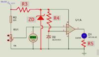
I drew in additional components.


ZD can be 5 V, if that is the value you choose to power the 358.

R3 will drop many volts. It may get hot. R3 should be high, but still allow the 358 to have a stable supply.

Select R4 so that 1-5 mA goes through D2.

As an alternate, substitute a potentiometer for D2 and R4.

At all times keep the op amp inputs at a lower voltage than the supply voltage.
 

overvoltage ckt.jpg

finally I made it in PROTEUS.When I simulate it,it activate at 53.1 volts,though I make it for 54.4 volts.Please tell me where is my fault?
 

When I simulate it,it activate at 53.1 volts,though I make it for 54.4 volts.Please tell me where is my fault?

You must dial the potentiometer. Fine-tune it for activation at the level you wish.

Also, this is unrelated, but I believe you can increase R1 several times. A zener diode only needs a few mA going through it, so it can provide a stable reference.
 

I have design many battery chargers cc and cv type, lead acid safe full level is 14v to 15v .but I normally leave it at 14.5v. For 4 batteries in series it will be 58v.for low cutoff is 11v(optimum)for 4 batteries is 44v(optimum).
 

Status
Not open for further replies.

Similar threads

Part and Inventory Search

Welcome to EDABoard.com

Sponsor

Back
Top