Continue to Site

Welcome to EDAboard.com

Welcome to our site! EDAboard.com is an international Electronics Discussion Forum focused on EDA software, circuits, schematics, books, theory, papers, asic, pld, 8051, DSP, Network, RF, Analog Design, PCB, Service Manuals... and a whole lot more! To participate you need to register. Registration is free. Click here to register now.

[SOLVED] Serial communication with Hyper Terminal.

Status
Not open for further replies.

Praveen Kumar P S

Member level 4
Joined
Aug 21, 2014
Messages
79
Helped
1
Reputation
2
Reaction score
1
Trophy points
8
Location
India
Activity points
627
Hello Guys....
Today i m having a new problem...

Here is my code::

Code:
#include <18f4550.h>
#device ADC=10
#fuses HS, PLL5, CPUDIV1, NOWDT, NOPROTECT, BROWNOUT, NOLVP, PUT, NOMCLR
#use delay(clock=20000000)
#use rs232(baud=19200, xmit=PIN_C6, rcv=PIN_C7,parity=N,bits=8,ERRORS)
#include<flex_lcd216.c>

void main()
{
float32 T , val;
delay_ms(500);
lcd_init();
lcd_setcursor_vb(1,1);
printf(lcd_putc,"\f ");
setup_comparator(NC_NC_NC_NC);
setup_adc_ports(AN0_TO_AN1);
setup_adc(ADC_CLOCK_DIV_8); 
for(;;)
{
set_adc_channel(0);
delay_ms(10);
T=read_adc();
delay_ms(100);
val=T*(4.26/1023)*100;
delay_ms(600);
lcd_gotoxy(1,1);
delay_ms(10);
printf(lcd_putc,"Tem Read:%3.5f ",val);
delay_ms(10);
printf("Tem Read:%3.1f\xDFC",val);
delay_ms(500);
output_toggle(PIN_D1);
delay_ms(10);
output_toggle(PIN_E1);
delay_ms(10);
}

}

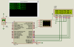
Here my lcd display shows the correct temperature...But when serially transmitted the hyper terminal i used shows random letters like this::


I m using realterm as hyper terminal...i also tried several other..but no effect...
i also run with several baurd rate...but no effect...

thank you..
 

In code baudrate is 19200 and in RealTerm baudrate is 57600. Change baudrate in RealTerm to 19200.

In printf statement you are using %3.5f and %3.1f. Do you know what it means ?

%3.5f means total of three digits and 5 digits after decimal point which is invalid. %3.1f means total of three digits and 1 digit after decimal point, so your output will be like xx.x

Temperature can go upto 150 deg C, So, you need to display like xxx.xx or xxx.x. So you should use %5.2f or %4.1f.
 
Last edited:

In code baudrate is 19200 and in RealTerm baudrate is 57600. Change baudrate in RealTerm to 19200.

In printf statement you are using %3.5f and %3.1f. Do you know what it means ?

%3.5f means total of three digits and 5 digits after decimal point which is invalid. %3.1f means total of three digits and 1 digit after decimal point, so your output will be like xx.x

Temperature can go upto 150 deg C, So, you need to display like xxx.xx or xxx.x. So you should use %5.2f or %4.1f.

Hi milan..
thanks for the replay..
I used a standard baurd rate of 9600 in both program and real term.but still the same....
I used 3.5f for more accuracy, but i changed it to 3.1 later in my program....but same

Latest Real term output::


Thank You..
 

Zip and post the complete CCS PIC C project files.
 

Are you using a Serial to TTL converter to communicate with the PC's Serial port?
 

Zip and post the complete CCS PIC C project files.

Hi milan..
Thanks for the replay..
Here is my complete project::

Thank you

- - - Updated - - -

Are you using a Serial to TTL converter to communicate with the PC's Serial port?

Thanks for the replay...
i dont think so...because no Max232 Ic is being used in my board..
 

Attachments

  • Adc_Pic18.zip
    72.1 KB · Views: 107

You need a MAX232 or a TTL to RS232 or TTL to USB converter if connecting through USB port to PC. I didn't find any UART code in your project.

Don't connect MCUs TTL UART pins directly to PC's RS232 port. You will damage MCUs UART.

Try attached code.
 

Attachments

  • Adc_Pic18.rar
    140.9 KB · Views: 105
  • adc uart lcd sim ss.png
    adc uart lcd sim ss.png
    53 KB · Views: 174

You need a MAX232 or a TTL to RS232 or TTL to USB converter if connecting through USB port to PC. I didn't find any UART code in your project.

Don't connect MCUs TTL UART pins directly to PC's RS232 port. You will damage MCUs UART.

Try attached code.

Hello milan..

my board comes with a Rs232 port...and i use a rs232 to usb converter for serial communication..
I tried your code still the same no change in the output...
what do you mean by UART code??
plz help me with UART code..

Thank You...
 

What frequency Crystal are you using ? I have posted the code. There was no Serial print code in your project.
 

If you are using 16 MHz crystal then why have you mentioned 48000000 for clock in code. Do you know what you are doing ?
 

Attachments

  • Adc_Pic18 16 MHz Crystal 9600 bps.rar
    157.1 KB · Views: 88
Last edited:

If you are using 16 MHz crystal then why have you mentioned 48000000 for clock in code. Do you know what you are doing ?

i dont know excatly the division of the clock is done....
But i tried to run it both 8 mhz and 20 mhz clock....still not working....could u plz tell me how the division of clock is done???

Thank YOu......
 

But i tried to run it both 8 mhz and 20 mhz clock

You said you were using 16 MHz. Then what is the use of testing with 8 MHz and 20 MHz. Baudrate generation depends upon Fosc (Crystal Frequency).

Crystal of 16 MHz is connected to OSC 1 and OSC2 pin and hence you are using Primary Oscillator. See fig. here. https://www.mikroe.com/forum/viewtopic.php?t=10646

You have to provide 4 MHz input to PLL circuit. It is a fixed value. So to get 4 MHz from 16 MHz you use prescalar divide by 4. (PLLDIV = PLL4 in fuses = 001) 16 MHz is divided by 4 and the o/p of prescalar is 4 MHz. This is fed to PLL circuit and it generates 96 MHz clock. This 96 MHz is again divided by 2 to get 48 MHz clock. This clock is used for USB.

Next comes the clock for processing.

The same 16 MHz is passed through oscillator postscalar to get desired frequency. To keep postscalar o/p 16 MHz we have to divide 16 MHz input by 1 (CPUDIV = CPUDIV1 = 00). Any Fosc > 4 MHz is HS. So, HS is used in fuses. This 16 Mhz from the postscalar is the primary clock for the device. Your baudrate is generated according to primary oscillator frequency. Try my previous code with 16 MHz crystal.

Hey milan...

i tried your previous code with 16Mhz clock...still not working....
here my primary oscillator frequency is 16MHz...how can i calculate the baurd rate...
thank you...
 

Hi Praveen Kumar P S,

What did you got from the above post, what did you tried by yourself ?

Just writing "not working", "not working" ..

Unless you understand it, It wont work.
 

You don't have to configure any thing manually to generate baudrate. Your CCS C Compiler will configure the registers. In your code it is set for 9600 bps. In RealTerm it should be 9600 bps selection. Post link of your Dev Board. Are you testing it on breadboard. If yes, that might be the problem. Try to solder the crystal and its associated ceramic capacitors and try. If you use 16 MHz crystal then use 27 pf or 33 pf Ceramin Capacitors for Crystal Circuit.
 

Hi Praveen Kumar P S,

What did you got from the above post, what did you tried by yourself ?

Just writing "not working", "not working" ..

Unless you understand it, It wont work.
hi Venkadesh..
Actually you have a point there..i did understand how to divide crystal frequency and use it for usb and primary clock...I said so because i did what he said and thought thier may some other problem as well....

Thank You

- - - Updated - - -

You don't have to configure any thing manually to generate baudrate. Your CCS C Compiler will configure the registers. In your code it is set for 9600 bps. In RealTerm it should be 9600 bps selection. Post link of your Dev Board. Are you testing it on breadboard. If yes, that might be the problem. Try to solder the crystal and its associated ceramic capacitors and try. If you use 16 MHz crystal then use 27 pf or 33 pf Ceramin Capacitors for Crystal Circuit.

No, i m not doing it on a breadboard. Its a board i brought from a local store...Its written PIC DEV BOARD on the back of the board...nothing else...In the board the crystal is connected through two resistor
Thank you..
 

Hi

Here I am telling you a easy way to solve the problems with baud rate in any controller.

To solve a baud rate problem you need two things.
1, Required baud rate (set in the code)
2, Actual baud rate (when UART working)

We all know the Required baud rate.

The set baud rate can be found in two ways.
1, Using Oscilloscope
2, Using Terminal

Using Oscilloscope:

max_exp_uart.png


This is a bit very easy method of finding the baud rate. You just need to transmit 0x55 continuously from your code.
And just measure a one bit period of the signal using oscilloscope
1/t is the baud rate.

Using Terminal:
For this technique, You will need a ASCII table. Just transmit the same 0x55 or 'U' for certain number of (about 100 times) from the controller.

**broken link removed**

set the required baud rate in the terminal and you will receive 100 'U' s if your baud rate is working correctly. otherwise you will get some different letter in different counts. by using the number of count and bit pattern of the received letter you can find the actual baud rate.

After finding the Actual baud rate, you can have the ratio of Actual and Required baudrate using that you can make the changes in CLK rate to get the baud rate working in required baud rate. This method will be also useful in case of working in a new controller which has lot of clock control options.
 
It has been very long i have been to edaboard as i having my exam.....
i have brought a new max232 ic and its now working very welll....actuallly there was a problem with my ownboard serial module...
Thank you all for helping me..........
 

Status
Not open for further replies.

Similar threads

Part and Inventory Search

Welcome to EDABoard.com

Sponsor

Back
Top